Potential balancing circuit for battery pack

A potential balancing and battery pack technology, applied in charge balancing circuits, battery circuit devices, circuit devices, etc., can solve the problems of complicated circuit control, energy loss, and high cost, and achieve the effect of reducing the number of uses

Inactive Publication Date: 2012-08-15
ACBEL POLYTECH INC
View PDF3 Cites 11 Cited by
  • Summary
  • Abstract
  • Description
  • Claims
  • Application Information

AI Technical Summary

Problems solved by technology

However, since the failure mode of the Zener diode 41 is a short circuit, not only energy will be lost, but also its dissipated power is limited by the size of the element, which becomes a major disadvantage.
[0005] 2. Resistance balance circuit: please refer to Figure 5 As shown, a resistor 51-54 is connected to one end of each series-connected battery, a switch 55-57 is connected between two adjacent resistors 51-54, and a controller 58 is used to determine the conduction and cut-off of each switch 55-57 , although this structure can achieve the purpose of power balance, it transmits the energy of the battery to the resistors 51-54 for consumption, and cannot effectively use the power of the battery as its main disadvantage
This method has high circuit efficiency and can quickly reach the power balance state of the battery, but it needs to accurately detect the potential state of each battery and determine the conduction sequence of different switches 62 and 63, so the circuit control is complicated and costly. The hardware requirements for detecting the potential state are high
[0007] 4. Capacitive balance: such as Figure 7 As shown, using switched capacitor technology to achieve power balance, but its main disadvantage is that the circuit control is complicated, which is the same as the problem of the aforementioned inductive balance
[0009] From the perspective of the aforementioned numerous types of battery balancing circuits, when there are N batteries in series, at least N switches or N-1 inductors need to be used, and N pulse width modulation signals are needed to control the N switches. The complexity and cost will increase significantly

Method used


Image

  • Potential balancing circuit for battery pack
  • Potential balancing circuit for battery pack
  • Potential balancing circuit for battery pack

Examples


Embodiment Construction

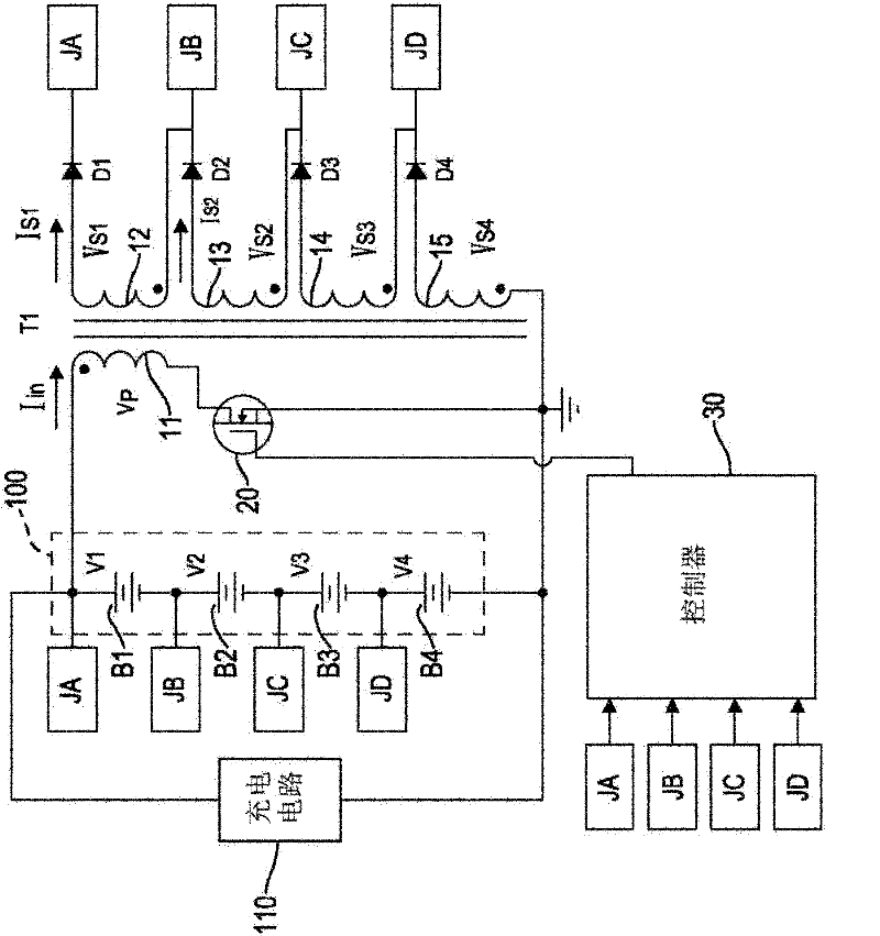
[0042] Please refer to figure 1 As shown, it is the first embodiment of the battery pack potential balancing circuit of the present invention, which is applied to balance the electric power between multiple series connected battery units B1-B4, and the multiple series-connected battery units B1-B4 form a battery pack 100, as follows Detailed description Taking four battery units B1~B4 as an example, each battery unit B1~B4 can be a single battery or composed of several batteries connected in series, and the battery units B1~B4 use a charging circuit 110 connected in series Charging work. The present invention includes:

[0043] A flyback transformer T1 has a primary side winding 11 and a plurality of secondary side windings 12-15. In this embodiment, the number of secondary side windings 12-15 is consistent with the number of battery cells B1-B4. The primary side One end of the winding 11 is connected to one end of the battery pack 100; each secondary side winding 12-15 has...


PUM


Abstract

The invention relates to a potential balancing circuit for a battery pack, and the potential balancing circuit for the battery pack can be used for balancing the electric power among battery units which are in series connection with each other inside the battery pack. The potential balancing circuit for the battery pack comprises a transformer, a changeover switch and a controller, wherein one end of a primary side winding of the transformer is connected with the battery pack, the other end of the primary side winding is in series connection with the controller, and the transformer is provided with a plurality of secondary side windings which can be respectively connected with the battery units. When the controller controls the changeover switch to be alternately switched on / off, the transformer extracts more energy from the battery units with higher potentials, and the energy is output by the secondary side windings in a coupling manner to charge the battery units with lower potentials, so that the function of power balancing can be exerted by using a simple circuit structure.

Description

technical field [0001] The invention relates to a potential balance circuit of a battery pack, in particular to a balance circuit with a relatively simple circuit structure which can balance the electric power between different batteries or battery packs. Background technique [0002] In order to adapt to various applications, batteries are often used in series or parallel. During the charging process, due to the series connection, the currents flowing through the same string of batteries are equal in size, which can make the charging current of the batteries consistent. However, due to differences in time, materials, manufacturing methods, and usage conditions, the potential and capacity of each battery are different, which will cause some batteries to be overcharged or some batteries to be undercharged. Judging the state of charge of the battery is generally based on the potential of the battery. When the battery is overcharged, the potential of the battery will exceed th...

Claims


Application Information

Patent Timeline
Patent Type & Authority Applications(China)
IPC IPC(8): H02J7/00
CPCH02J7/0016
Inventor 王仕元
Owner ACBEL POLYTECH INC
Why Eureka
Try Eureka