Eureka AIR delivers breakthrough ideas for toughest innovation challenges, trusted by R&D personnel around the world.

Motor-gear unit with integrated eccentric wheel gear

a technology of eccentric wheel gear and motor gear, which is applied in the direction of gears, mechanical equipment, mechanical energy handling, etc., can solve problems such as unsuitability for applications

Inactive Publication Date: 2003-12-09
ROBERT BOSCH GMBH
View PDF14 Cites 16 Cited by
  • Summary
  • Abstract
  • Description
  • Claims
  • Application Information

AI Technical Summary

Benefits of technology

The motor-gear unit according to the invention having the characteristics of the main claim has the advantage of extremely great compactness, since the eccentric wheel gear is disposed in a free installation space of the rotary drive. By integrating the gear with the drive, the structural length of the unit is reduced considerably and can be selected to be quite small compared to its diameter.A further advantage of the integration of the gear according to the invention is that imbalance forces occurring during operation at the eccentric wheel can be compensated for very simply and precisely by means of suitable counterweights on the rotary drive.By means of the characteristics recited in the dependent claims, advantageous refinements of the motor-gear unit defined by the main claim are possible.An especially compact design of the motor-gear unit is attained if the eccentric wheel gear is surrounded by a rotor of the rotary drive. The inside diameter of the rotor is selected to be great enough that there is space for the gear inside this diameter. The gear can thus be inserted all the way into the drive, and an especially advantageous shallow design is attained.It is also advantageous if the at least one guide bolt, which assures the eccentric motion of the eccentric wheel and prevents undesired rotation of the eccentric wheel, is disposed on a housing part that divides the free installation space from the rotary drive. Thus the guide bolts that are required to operate the eccentric wheel and that advantageously guide the eccentric wheel can be integrated with the motor-gear unit as well.If this at least one guide bolt protrudes into a preferably circular recess on the eccentric wheel, then the eccentric motion of the eccentric wheel is assured, yet at the same time rotation of the eccentric wheel is prevented.If the inside width of the recess in the eccentric wheel is equivalent to twice the eccentricity of the eccentric element, then the at least one guide bolt can roll along the wall of the recess, and the desired guidance effect is made possible in an optimal way.It is also advantageous if a plurality of guide bolts are disposed, symmetrically, about the eccentric wheel on the housing part. It has been demonstrated in practice that a uniform power takeoff rpm is attained by means of at least three bolts offset from one another by an angle of 120.degree.. If the number of bolts is increased further, then not only is the synchronous operation of the motor-gear unit improved, but the forces operative in operation and thus the mechanical stresses are also distributed uniformly to the individual bolts.The intermittent meshing of the eccentric wheel with the driver is advantageously attained in that the eccentric wheel has an internal toothing and the driver has an external toothing.In an especially advantageous variant, the rotary drive is an electronically commutated motor.If the eccentric element is formed directly onto the rotor, then the two components can advantageously be made in one piece.

Problems solved by technology

It is unsuited to applications where there is severely restricted installation space, for instance for sunroofs or window control systems in motor vehicles.

Method used


Image

  • Motor-gear unit with integrated eccentric wheel gear
  • Motor-gear unit with integrated eccentric wheel gear
  • Motor-gear unit with integrated eccentric wheel gear

Examples


Embodiment Construction

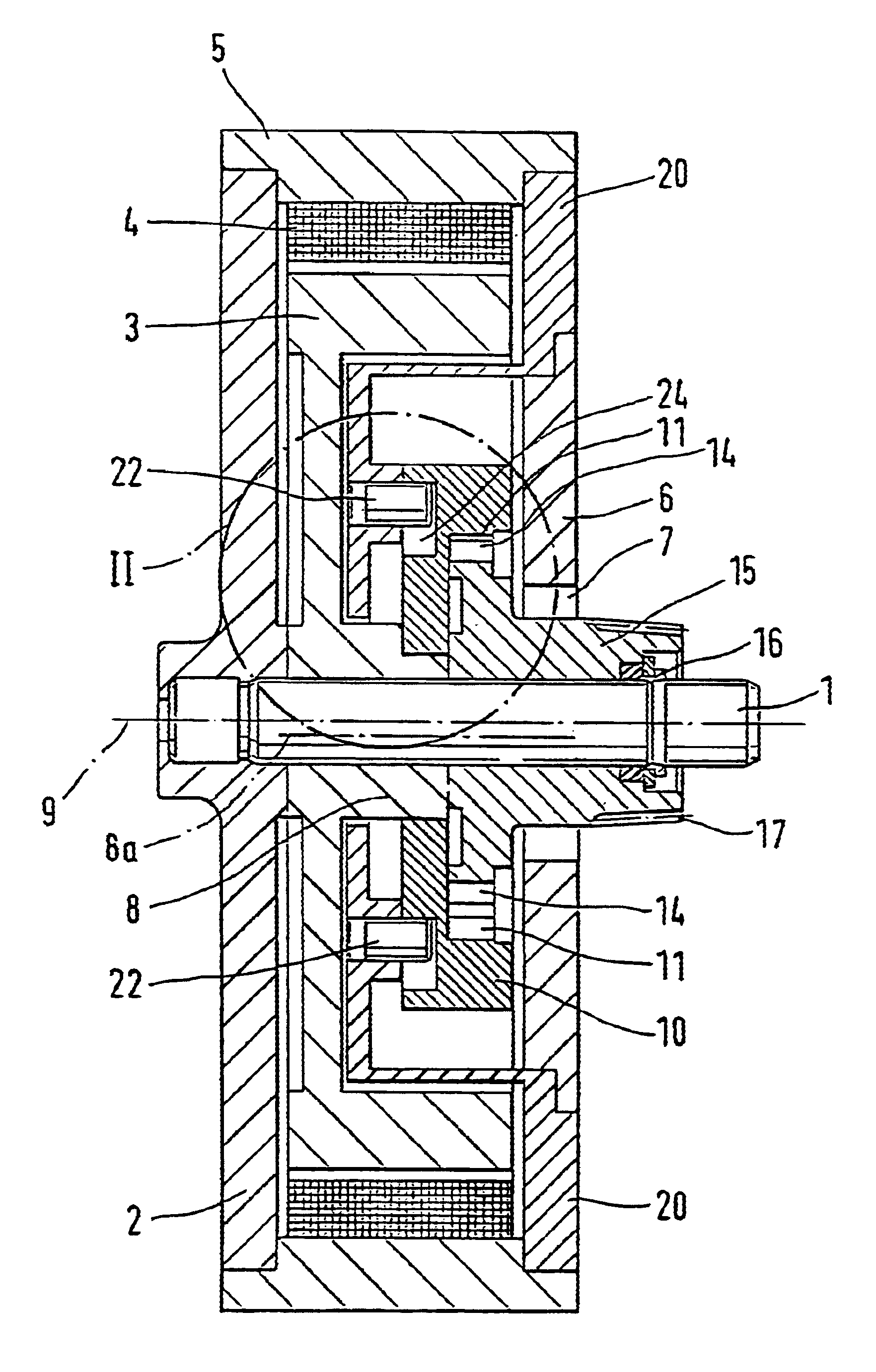
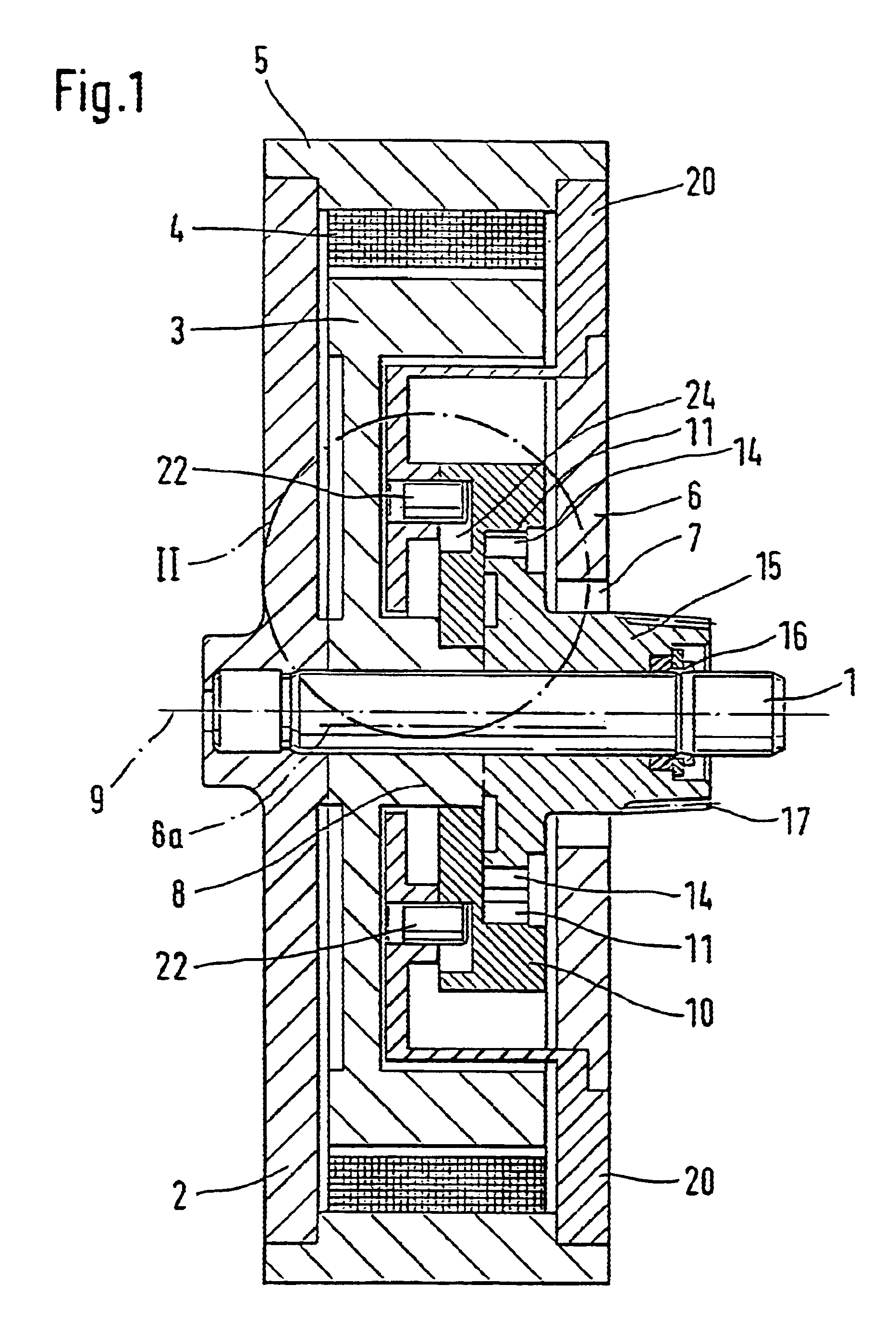
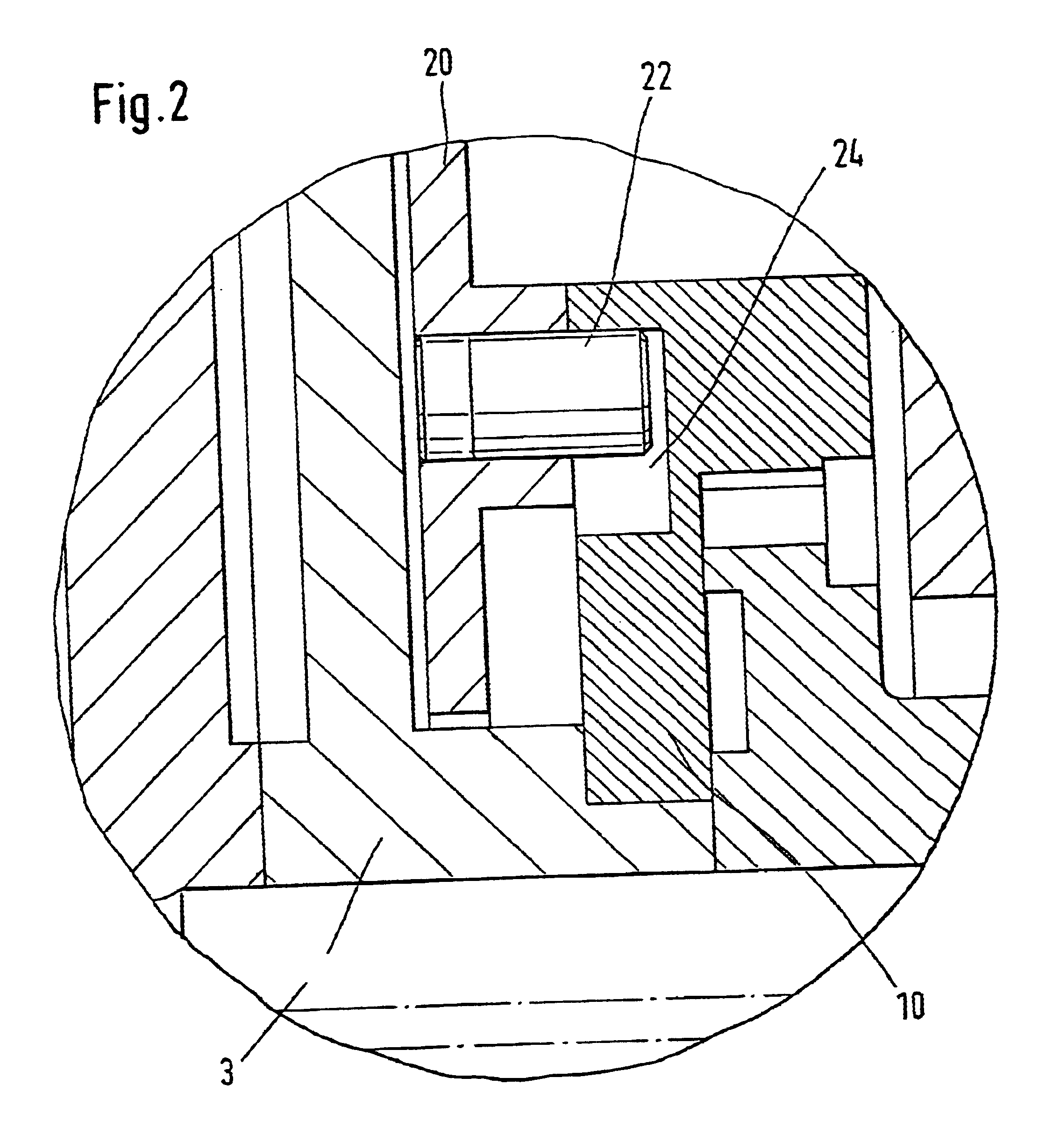
The exemplary embodiment, shown in FIG. 1, of a motor-gear unit according to the invention shows an electric motor with an eccentric wheel gear, which has a shaft 1 that is secured in a housing bottom 2 in a manner fixed against relative rotation. A rotary drive with a rotor 3 is rotatably disposed on the shaft 1 and is driven by coils 4 of the electric motor. The coils 4 are disposed on the inside in a cylindrical housing portion 5, and the housing bottom 2 is also secured to the housing portion 5. On the side of the housing portion 5 opposite the housing bottom 2, a housing part 6 in the form of a cap with a central opening 7 is mounted in fixed fashion. The end of the shaft 1 remote from the housing bottom 2 protrudes through this central opening 7.

The housing portion 5, housing bottom 2, and cap 6 form a motor housing, in whose interior the rotor 3 is disposed, which is rotatable on the shaft 1 and is provided with an eccentric element 8 that extends axially along the center axi...


PUM


Abstract

A motor-gear unit, having an eccentric wheel gear, driven by a rotary drive (3), which eccentric wheel gear has an eccentric element (8), an eccentric wheel (10) rotatably supported on the eccentric element, and a driver (15), and the driver (15) cooperates with the eccentric wheel (10) by intermittent meshing, further having at least one guide bolt (22), which cooperates with the eccentric wheel (10) and both assures the eccentric motion of the eccentric wheel (10) and prevents an undesired rotation of the eccentric wheel 10. It is proposed that the eccentric wheel gear is disposed in a free installation space of the rotary drive (3).

Description

PRIOR ARTThe invention relates to a motor-gear unit, having an eccentric wheel gear driven by a rotary drive, as generically defined by the preamble to the main claim.To reduce the rotary speed of control motors with an armature rpm of about 7000 revolutions per minute, worm gears are often used. These worm gears, which are driven by electric motors, are distinguished by having self-inhibition from the power takeoff side. Because of the necessarily high gear ratio required to attain adequate torques, for instance to drive window controls or a sunroof in a motor vehicle, the external dimensions of an adjusting motor, comprising a motor and gears disposed side by side, is considerable.Other types of gear, used in so-called friction-drum motors, are known, for instance from German Patent Disclosure DE 196 18 248. These friction-drum motors have a tubular motor housing, which surrounds a drum-type armature with an eccentric wheel gear disposed downstream of it. Using eccentric wheel gea...

Claims


Application Information

Patent Timeline
Patent Type & Authority Patents(United States)
IPC IPC(8): F16H1/32H02K7/116
CPCH02K7/116F16H1/32
Inventor MOSKOB, FRANK
Owner ROBERT BOSCH GMBH
Why Eureka
Eureka Blog
Learn More