Electric scissor motor

A technology for electric shears and motors, which is applied to electric components, electromechanical devices, electrical components, etc., can solve the problems of large occupation volume, high manufacturing cost, and difficult to dissipate heat, and achieve large torque output, low manufacturing cost, and good heat dissipation effect. Effect

Inactive Publication Date: 2014-09-03
王火标
View PDF4 Cites 4 Cited by
  • Summary
  • Abstract
  • Description
  • Claims
  • Application Information

AI Technical Summary

Problems solved by technology

[0005] 2. The rotor 12 rotates in a closed space covered by the fixing seat 10, and since it is not easy to dissipate heat, it will reduce the service life of the electric shear motor 100
[0006] 3. A winding 123 configured on the rotor 12 occupies a large volume, resulting in a large amount of winding materials and high manufacturing costs

Method used


Image

  • Electric scissor motor
  • Electric scissor motor
  • Electric scissor motor

Examples


Embodiment Construction

[0015] The present invention will be described in detail below in conjunction with the accompanying drawings and embodiments.

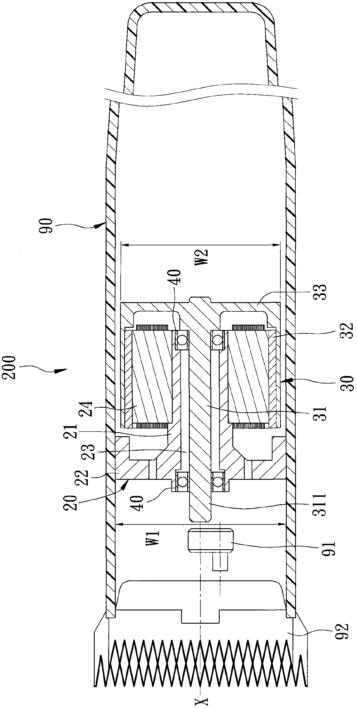
[0016] Such as figure 2 As shown, the first preferred embodiment of the electric shear motor 200 of the present invention includes a fixing base 20 , a rotor unit 30 , and two bearings 40 .

[0017] The fixing seat 20 is used to be fixed in an electric scissors housing 90, and includes a surrounding wall 21 extending along an axis X and surrounding it, a fixing wall 22 extending radially from the surrounding wall 21, and a fixed wall 22 formed on the surrounding wall 21. A mandrel hole 23 extending along the axis X in the surrounding wall 21 , and a winding 24 sleeved on the outer peripheral surface of the surrounding wall 21 along the axis X.

[0018] The fixed wall 22 is close to one end of the surrounding wall 21, and a fixed seat width W1 formed by the fixed wall 22 in the radial direction is greater than a rotor width W2 formed by the rotor uni...


PUM


Abstract

The invention relates to an electric scissor motor which comprises a fixing seat, a rotor unit and two bearings. The fixing seat comprises a surrounding wall, a fixing wall, a mandrel hole and a winding, wherein the surrounding wall extends along and surrounds an axis, the fixing wall extends from the surrounding wall along the radial direction, the mandrel hole is formed in the surrounding wall and extends along the axis, and the winding is sleeved on the outer peripheral face of the surrounding wall along the axis; and the winding and the fixing wall are arranged at an interval along the axis. The rotor unit comprises a mandrel, a magnetic ring and a force arm, wherein the mandrel penetrates through the mandrel hole along the axis, the magnetic ring surrounds the winding, and the force arm extends from the mandrel along the radial direction and is connected with the magnetic ring. The bearings are respectively arranged at the two ends of the surrounding wall and are connected between the surrounding wall and the mandrel.

Description

technical field [0001] The invention relates to a motor structure, in particular to an electric shear motor applied to electric shears. Background technique [0002] Such as figure 1 As shown, the existing electric shear motor 100 mainly includes a fixed base 10 for fixing in an electric shear housing 90, a magnetic ring 11 arranged in the fixed base 10, and a magnetic ring covered by the fixed base 10. And the rotor 12 surrounded by the magnetic ring 11 has a connecting portion 121 protruding from the fixed seat 10, the connecting portion 121 is used to connect an eccentric wheel 91, and the rotor 12 can drive the eccentric wheel 91 when rotating. Drive a blade 92 to reciprocate, to provide the effect of cutting hair. [0003] However, the electric shear motor 100 has the following disadvantages: [0004] 1. The arm length of the rotor 12 radially extending from a mandrel 122 is limited by the structure of the magnetic ring 11 and the holder 10. Since the length of the a...

Claims


Application Information

Patent Timeline
Patent Type & Authority Patents(China)
IPC IPC(8): H02K5/04H02K1/22H02K7/075H02K9/04
Inventor 王火标
Owner 王火标
Why Eureka
Try Eureka