
Technology for machining stator/rotor punching piece

A processing technology, stator and rotor technology, applied in the field of stator and rotor punching processing technology, can solve the problems of labor intensity, long labor hours, inability to adapt to mass production, low work efficiency, etc., to achieve improved production efficiency, simple and accurate positioning, The effect of reducing labor intensity

Inactive Publication Date: 2012-08-15
JIANGSU TONGDA POWER TECH
View PDF5 Cites 2 Cited by
  • Summary
  • Abstract
  • Description
  • Claims
  • Application Information

AI Technical Summary

Problems solved by technology

This kind of operation method requires a variety of process holes or process keys, which has low work efficiency, labor intensity, long man-hours, and high energy consumption, and cannot be adapted to mass production.

Method used


Image

  • Technology for machining stator/rotor punching piece
  • Technology for machining stator/rotor punching piece
  • Technology for machining stator/rotor punching piece

Examples


Embodiment Construction

[0019] The attached drawing discloses a structural schematic diagram of a preferred embodiment of the present invention without limitation, and the technical solution of the present invention will be described in detail below in conjunction with the accompanying drawings.

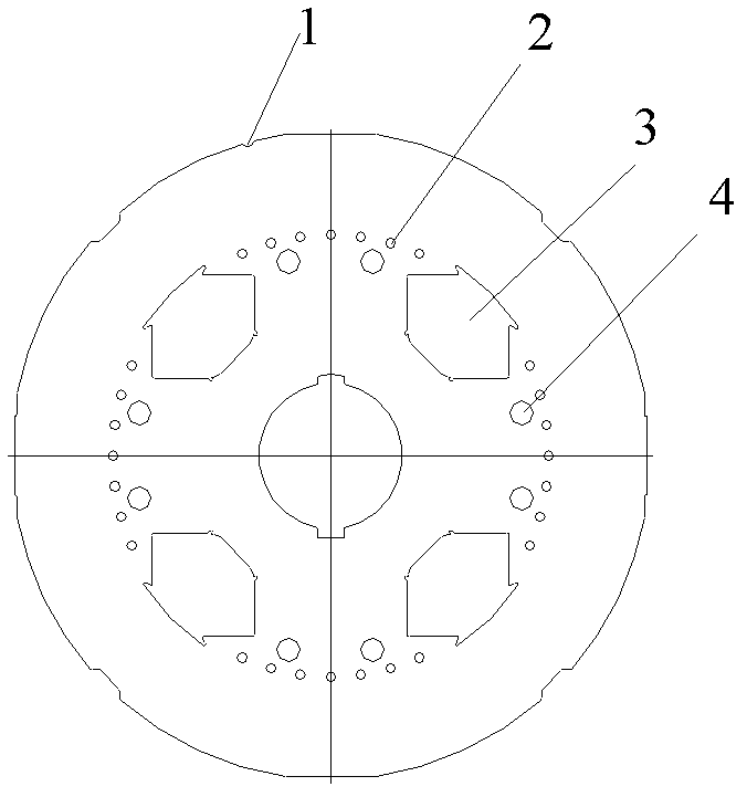
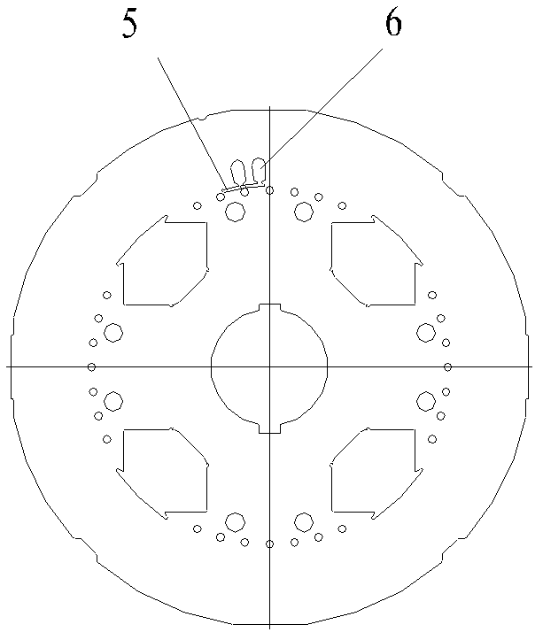
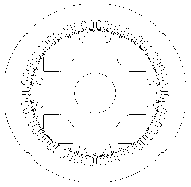
[0020] Figure 1 to Figure 3 It is a schematic diagram of the product structure corresponding to each step of the stamping process of the stator and rotor of the present invention. Stamping and stamping process of stator and rotor according to the present invention includes the following steps: (1) Blanking of stator and rotor: adjusting equipment, correctly installing and debugging the blanking die of the product, positioning and blanking according to the material width, used for stator outer circle belt To distinguish the marking groove 1 on the front and back and the material-saving trimming, and simultaneously punch the shaft hole, the damping hole 2, the support rod hole 4, and the four embedding groov...


PUM


Abstract

The invention discloses a technology for machining a stator / rotor punching piece, comprising the following steps of: (1) blanking a stator and a rotor: positioning by the width of plate material, and blanking the outline of the stator, a shaft hole and a rotor groove shape, wherein the rotor groove shape comprises four wire embedding grooves; and (2) punching a stator belt and cutting an air gap: positioning by the wire embedding grooves, synchronously and repeatedly punching a stator groove shape and an air gap between the stator and the rotor, so that the stator punching piece is separated from the rotor punching piece. The four wire embedding grooves are distributed in the manner of ring array; and the rotor groove shape further comprises a damping hole and a support rod hole. The stator outline in the step (1) comprises a mark groove, which is used for distinguishing the front side of plate material from the back side of plate material. The labor intensity of operating personnel can be reduced, and the working capacity of the operating personnel can be reduced, so that the technology is superior in quantity production. The punching technology is time-saving and labor-saving, so that the conventional technology is changed, and the rotor groove shape is formed once, the production efficiency is improved, so that the high-efficiency production can be achieved.

Description

technical field [0001] The invention relates to a stator and rotor stamping process, which is suitable for the stator and rotor stamping process, and belongs to the field of stator and rotor stamping manufacturing for motors and generators. Background technique [0002] In the prior art, the stamping process of the stator and rotor generally consists of three steps: (1) traditional blanking: punching the shaft hole, the keyway, and the outer circle of the stator; (2) punching the stator slot, trimming and separating the rotor; (3) punching Rotor punching slot. This kind of operation mode requires multiple process holes or process keys, which has low work efficiency, labor intensity, long man-hours, and high energy consumption, and cannot be adapted to mass production. Contents of the invention [0003] The invention aims at the deficiencies of the prior art, and provides a stamping process of stator and rotor with simple process and reduced production cost. [0004] The ...

Claims


Application Information

Patent Timeline
IPC IPC(8): H02K15/02
Inventor 程国栋王春雷马艳萍
Owner JIANGSU TONGDA POWER TECH
Learn More