
Air motor and electrostatic coating device

A technology of air motors and nozzles, applied in electrostatic spraying devices, spraying devices, spraying devices with movable outlets, etc., can solve problems such as protruding, and achieve the effect of improving driving efficiency

Active Publication Date: 2012-08-15
NSK LTD
View PDF3 Cites 9 Cited by
  • Summary
  • Abstract
  • Description
  • Claims
  • Application Information

AI Technical Summary

Problems solved by technology

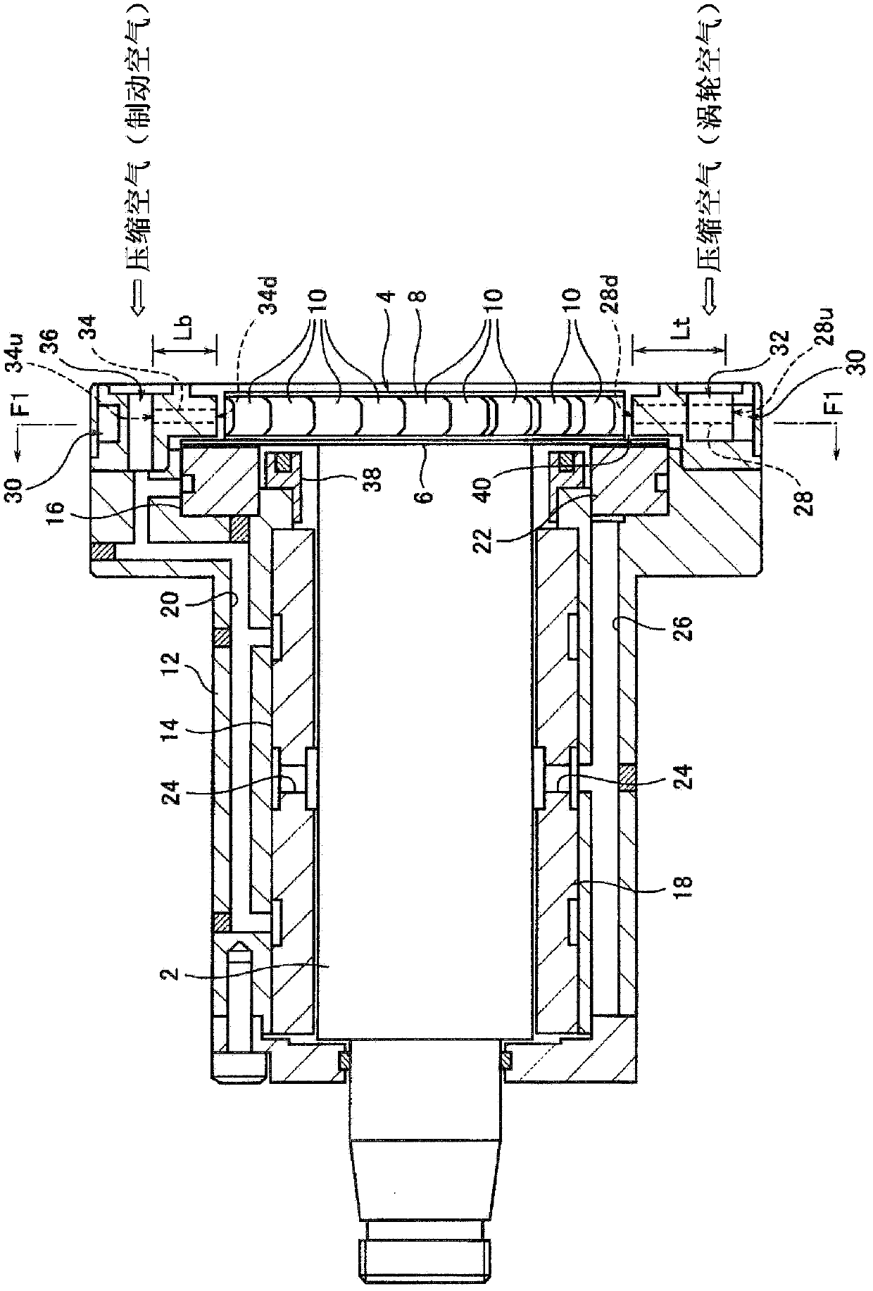
This is because, if figure 1 As shown, since the thrust bearing 16 is only provided on the output side of the rotary motion, there is a possibility that the main shaft 2, the impeller 4 and the impeller main body 8 are protruded to the opposite side of the output side of the rotary motion (the direction opposite to the output side of the rotary motion) possibility

Method used


Image

  • Air motor and electrostatic coating device
  • Air motor and electrostatic coating device
  • Air motor and electrostatic coating device

Examples


Embodiment Construction

[0075] Next, one embodiment of the air motor of the present invention will be described with reference to the drawings. In addition, the air motor of this embodiment can be assumed to be, for example, mounted on a spindle device used in an electrostatic spraying process, or a drive unit such as a spindle of a machine tool using a small-diameter tool that requires high-speed rotation, but the mounted device is not limited to these devices.

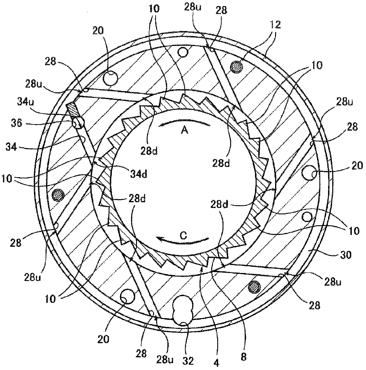
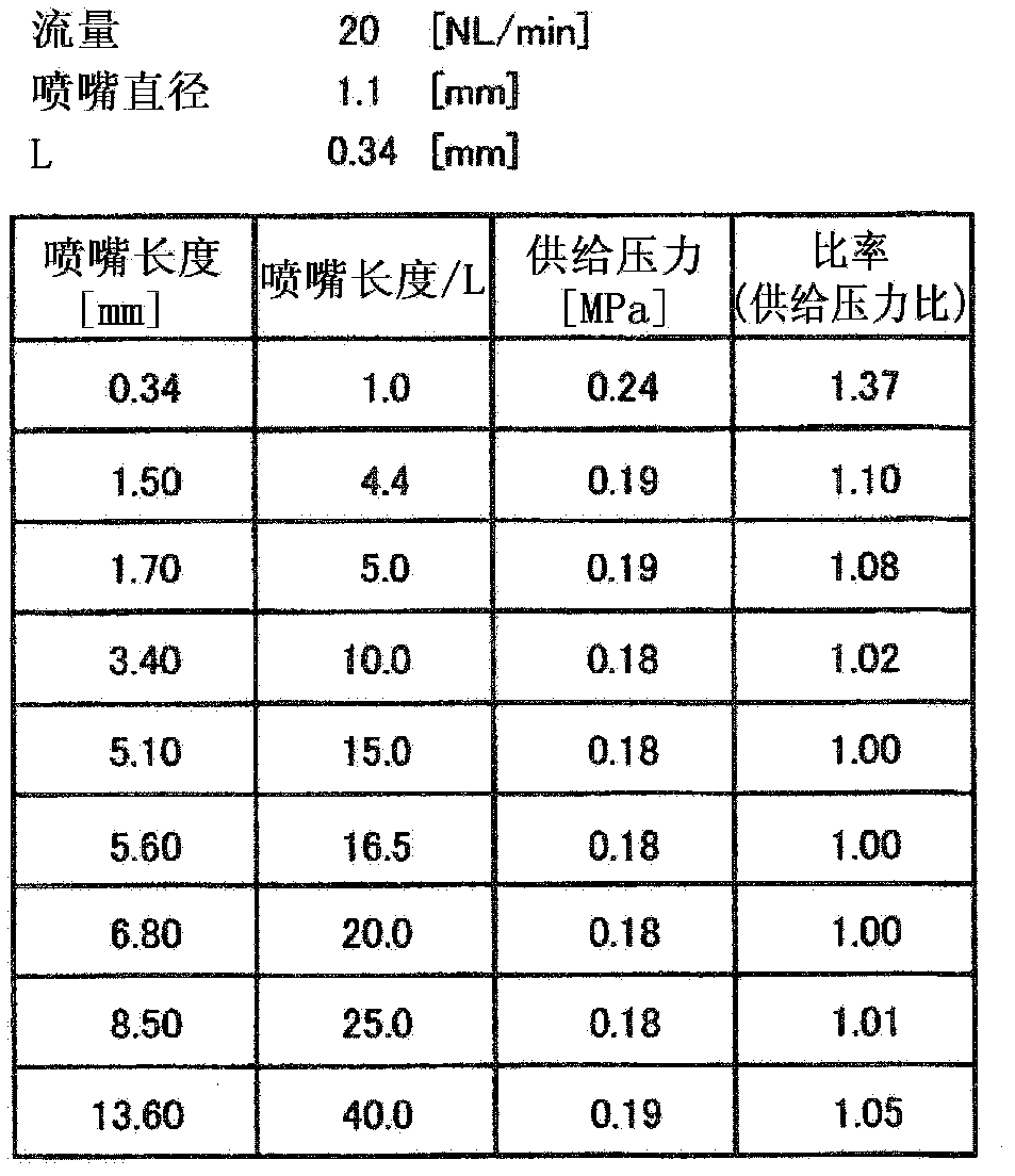
[0076] Furthermore, the air motor of this embodiment limits the length (nozzle length) of the nozzle portion constituting such an air motor to a size within a predetermined range, and the basic structure other than the nozzle portion of the air motor does not have the structure of a known air motor. question. Therefore, in this embodiment, the structure of the air motor (spindle device with air turbine) mounted on the electrostatic spray gun of the electrostatic sprayer as described above ( figure 1 and figure 2 ) is assumed to be an ex...


PUM


Abstract

Provided are an air motor and an electrostatic coating device which have improved efficiency. For this, the air motor and the electrostatic coating device comprise: a housing (12); a main shaft (2) which is inserted in the housing (12); a impeller (4) which has a part thereof disposed in the housing and fixed coaxially with the main shaft, the impeller (4) including a plurality of turbine vanes (10) formed along the outer circumferential surface thereof; bearings (14, 16) for rotatably supporting the main shaft and the impeller; and a nozzle part (a turbine air nozzle hole (28) and a brake air nozzle hole (34)) which includes a flow passage shaped like a tube or hole for blowing compressed air toward the turbine vanes to rotate the impeller in the circumferential direction. The length of the flow passage of the nozzle part is set to be equal to or greater than a value (L) calculated by a predetermined numerical formula constituted by the hydraulic radius (rh) of the flow passage of the nozzle part, the viscous friction coefficient (cf) of the surface of the flow passage, the ratio of specific heat (k) of the compressed air, the velocity (ve) of the compressed air at an inlet of the flow passage, the speed of sound (a0), and M1=ve / a0.

Description

technical field [0001] The present invention relates to an air motor and an electrostatic spraying device mounted, for example, on a spindle device used in an electrostatic spraying process, or a drive unit of a spindle system of a machine tool using a small-diameter tool that requires high-speed rotation. Background technique [0002] The air motor is a prime mover in which the main shaft is supported by a static pressure gas bearing, and gas such as compressed air is ejected from a nozzle portion (hole or pipe, etc.) toward an impeller (rotary blade) to rotate the main shaft. The air motor is widely used Mounted on electrostatic spraying machines and precision machining machines. In addition, in order to improve the rotation efficiency, various improvements have been made conventionally, and various motor structures in which the improvements have been realized are known (refer to Patent Document 1 and Patent Document 2). [0003] exist figure 1 and figure 2 In , as a s...

Claims


Application Information

Patent Timeline
Patent Type & Authority Applications(China)
IPC IPC(8): F01D1/06
CPCF01D1/023F01D1/06B05B3/002B05B5/0415B05B3/003B05B5/03F01D1/026
Inventor 小林直也中村刚小岩有
Owner NSK LTD
Learn More