Hall chip forming tool

A Hall chip, forming tooling technology, applied in metal processing, terminal application devices, etc., can solve the problems of damage to the capacitor part and chip part of the Hall chip, slow down the running speed, etc., to ensure displacement accuracy, ensure stability, reduce cost effect

Inactive Publication Date: 2012-08-22
安徽睿联测控技术有限公司
View PDF5 Cites 13 Cited by
  • Summary
  • Abstract
  • Description
  • Claims
  • Application Information

AI Technical Summary

Problems solved by technology

[0007] The purpose of the present invention is to provide a Hall chip forming tool, which is used to bend and cut the Hall chip by one-time fixing and multiple forming methods, so as to solve the need for secondary fixing and two-time forming in the existing bending forming device. The secondary molding production method is easy to increase the deformation of the Hall chip during the transfer process, resulting in damage to the capacitor part and the chip part of the Hall chip; at the same time, the sp

Method used


Image

  • Hall chip forming tool
  • Hall chip forming tool
  • Hall chip forming tool

Examples


Embodiment Construction

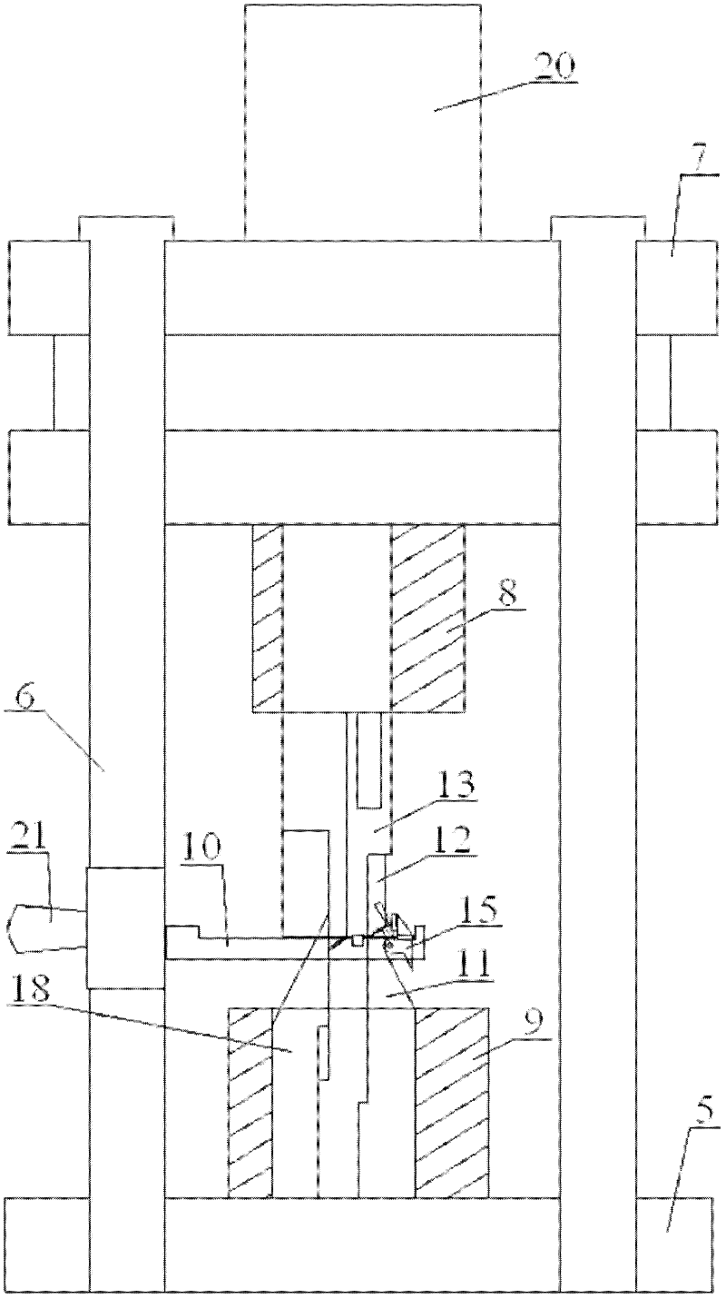
[0028] Referring to the accompanying drawings, referring to the accompanying drawings, a Hall chip forming tooling includes a lower mold base 5, four guide pillars 6 are respectively fixed around the upper surface of the lower mold holder 5, and the four guide pillars 6 are fitted by sliding An upper mold base 7 is installed, and upper and lower fixing blocks 8, 9 are respectively elastically installed above the upper and lower mold bases 7, 5, and feed guide grooves 10 are fixedly installed between the four guide pillars 6, and feed guide grooves The middle part of 10 is provided with an opening, and the lower fixed block 9 is fixedly equipped with a support seat 11, and the support seat 11 extends from the opening in the middle part of the feeding guide groove 10; Upper die pressing block 12,13, upper blade and upper die pressing block 12,13 are positioned at the top of support seat 11, wherein the end of upper blade 12 has wedge-shaped knife edge 14, is positioned at the low...


PUM


Abstract

The invention discloses a Hall chip forming tool comprising an upper die holder, a lower die holder, a plurality of guide pillars and a feeding guide slot, wherein the upper die holder and the lower die holder are respectively provided with an upper die block assembly and a lower die block assembly; the upper die block assembly comprises an upper die fixing block, an upper blade and an upper die pressing block; the lower die block assembly comprises a lower die fixing block, a lower blade, a lower die pressing block and a lower die forming block; the end of the lower die fixing block is provided with a hinge and a cam, and the cam is right positioned under the hinge to be matched with the hinge; and the upper die holder is provided with an air cylinder, and a piston rod of the air cylinder is fixedly connected to the upper surface of the upper die holder. The Hall chip forming tool disclosed by the invention adopts a once fixation and multi-forming mode so as to avoid the damage to a chip part and a capacitor part. The structure of the Hall chip forming tool is once fixed by adopting a spring buffering method so as to prevent a Hall chip pin from being pressed to be transformed. In addition, the Hall chip forming tool disclosed by the invention adopts a hinge structure to assist 90 DEG forming, so that the production efficiency is enhanced.

Description

technical field [0001] The invention relates to the field of Hall chip production and processing equipment, in particular to a Hall chip molding tool. Background technique [0002] The Hall effect is a magnetoelectric effect, which was discovered by the German physicist Hall in 1879 when he studied the nature of the force on a current-carrying conductor in a magnetic field. According to the Hall effect, people use semiconductor materials to make Hall elements. It has the advantages of sensitivity to magnetic field, simple structure, small size, wide frequency response, large output voltage change and long service life. Therefore, it is widely used in measurement, automation, computer and Information technology and other fields have been widely used. [0003] In recent years, with the development of the automobile industry, Hall devices have been widely used in the field of auto parts. The output of Hall devices is directly interfaced with the electronic control unit to ...

Claims


Application Information

Patent Timeline
IPC IPC(8): B21F1/00B21F23/00B26D1/09
CPCH01G13/006
Inventor 刘辽东殷宏斌刘超范云
Owner 安徽睿联测控技术有限公司
Why Eureka
Try Eureka