Loading and unloading device for engine cylinder block machining

An engine block and cylinder block technology, which is applied in metal processing and other directions, can solve problems such as hidden dangers in production safety, affecting the machining accuracy of the cylinder block, and the falling of the cylinder block.

Active Publication Date: 2015-02-04
BAODING WEIYI AUTOMOBILE CO LTD
View PDF5 Cites 1 Cited by
  • Summary
  • Abstract
  • Description
  • Claims
  • Application Information

AI Technical Summary

Problems solved by technology

[0002] At present, there are two loading and unloading methods suitable for machining engine cylinder blocks. One is to automatically pick up the cylinder block by the manipulator and place the cylinder block on the machine tool fixture according to a fixed path. Due to the high equipment cost and large space , can only be used with a production line with a high degree of automation; the other is that the operator uses a cantilever spreader to clamp the cylinder through the tensioning or clamping device on the spreader, and moves the spreader and the cylinder to the Near the fixture of the machine tool, place the cylinder on the fixture after aligning the position. Since the spreader has no guiding mechanism, it is very easy to bump the positioning surface or positioning pin hole of the cylinder when placing the cylinder, which will affect the machining accuracy of the cylinder. In addition, the spreader The hoisting height is relatively high, the cylinder body may fall, and there are hidden dangers in production safety.

Method used


Image

  • Loading and unloading device for engine cylinder block machining
  • Loading and unloading device for engine cylinder block machining
  • Loading and unloading device for engine cylinder block machining

Examples


Embodiment Construction

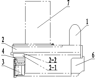
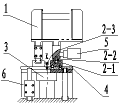
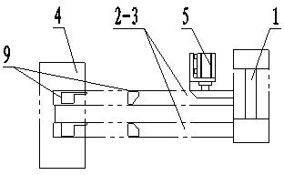
[0022] See Figure 1, Figure 2, image 3 , the present invention comprises a cylinder body lifting control unit 1, a cylinder body translation mechanism 2, a translation locking mechanism 5, a fixed bracket 4, a cylinder body lifting mechanism 3 and a base 6, and the cylinder body lifting control unit 1 is arranged on the cylinder body translation mechanism 2, the workpiece 7 is conveyed to the top of the cylinder body translation mechanism 2 by the raceway, the cylinder body translation mechanism 2 is assembled with the translation locking mechanism 5, and the cylinder body translation mechanism 2 is installed on the top of the fixed bracket 4. The bottom surface of the fixed bracket 4 is assembled with the cylinder lifting mechanism 3 , and the cylinder lifting mechanism 3 is installed on the base 6 .

[0023] See Figure 1, Figure 5 , Image 6 , the cylinder lifting control unit 1 of the present invention is composed of a rotating shaft 1-1, a rotating shaft bearing 1-3 an...


PUM


Abstract

A loading and unloading device for engine cylinder block machining is used for solving the problem of loading and unloading of the engine cylinder block machining. The loading and unloading device comprises a cylinder block hoisting control unit, a cylinder block translation mechanism, a translation locking mechanism, a fixing support, a cylinder block hoisting mechanism and a base, wherein the cylinder block hoisting control unit is arranged at one end of the cylinder block translation mechanism, a workpiece is delivered to the cylinder block translation mechanism through a raceway, the cylinder block translation mechanism and the translation locking mechanism are installed in a matching mode, the cylinder block translation mechanism is installed on the fixing support, and the bottom surface of the fixing support and the cylinder block hoisting mechanism are installed in a matching mode, and the cylinder block hoisting mechanism is installed on the base. The loading and unloading device for the engine cylinder block machining has the advantages of being convenient to operate, accurate in positioning, safe and reliable, low in equipment cost investment, and small in occupied space; not only the accuracy of positioning of engine cylinder block workpieces is improved, the machining quality of the workpieces is guaranteed, but also cylinder block falling accidents are avoided, and the hidden danger in safety production aspects is eliminated.

Description

technical field [0001] The invention relates to a loading and unloading device for machining workpieces, especially suitable for loading and unloading operations of engine cylinder processing, and belongs to the technical field of engines. Background technique [0002] At present, there are two loading and unloading methods suitable for machining engine cylinder blocks. One is to automatically pick up the cylinder block by the manipulator and place the cylinder block on the machine tool fixture according to a fixed path. Due to the high equipment cost and large space occupation , can only be used with a production line with a high degree of automation; the other is that the operator uses a cantilever spreader to clamp the cylinder through the tensioning or clamping device on the spreader, and moves the spreader and the cylinder to the Near the fixture of the machine tool, place the cylinder on the fixture after aligning the position. Since the spreader has no guiding mechani...

Claims


Application Information

Patent Timeline
Patent Type & Authority Patents(China)
IPC IPC(8): B23Q7/00
Inventor 景建军张松鹤丁春生庞旭
Owner BAODING WEIYI AUTOMOBILE CO LTD
Why Eureka
Try Eureka