Law of motion of a film timing made up of elementary functions

A technique of elementary functions and laws of motion, applied in the field of obtaining the laws of motion of foil beats from elementary functions

Inactive Publication Date: 2012-08-22
HEIDELBERGER DRUCKMASCHINEN AG
View PDF9 Cites 2 Cited by
  • Summary
  • Abstract
  • Description
  • Claims
  • Application Information

AI Technical Summary

Problems solved by technology

However, if the user wishes to change the law of motion of the transfer foil, this is either not possible at all or can only be achieved with great effort and / or only to a limited extent, since in particular the law of motion has to be completely recalculated

Method used


Image

  • Law of motion of a film timing made up of elementary functions
  • Law of motion of a film timing made up of elementary functions
  • Law of motion of a film timing made up of elementary functions

Examples


Embodiment Construction

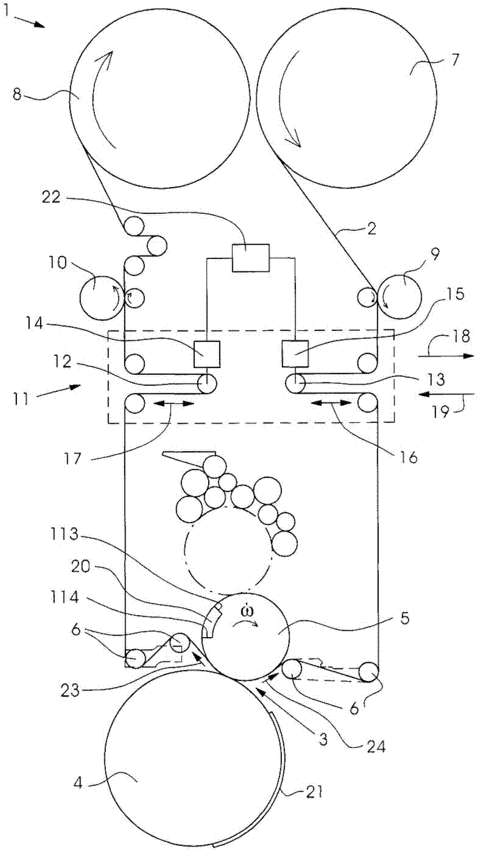
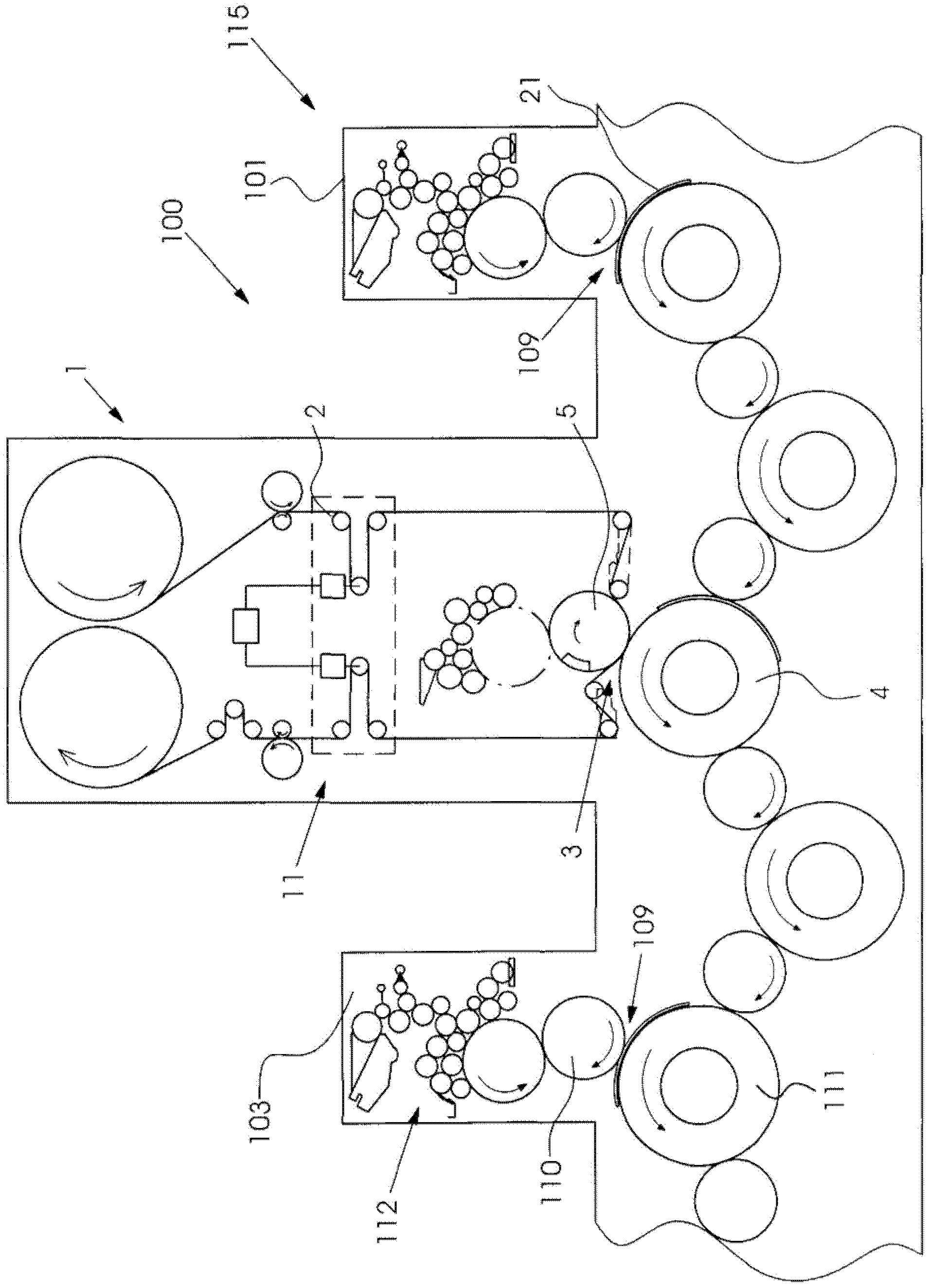
[0031] exist figure 1 shows a foil transfer device 1 in which a transfer foil 2 is guided through a transfer nip 3 .

[0032] The transfer gap 3 is formed by the transfer roller 5 and the counter roller 4 . The transfer foil 2 is unwound from the supply roll 7 and pulled by a front puller 9 in the direction of the transfer nip 3 . The supply roll 7 rests on a friction shaft (not shown here) and is driven at a speed that is lower than the speed of the printing material 21 . The drive of the supply roll 7 takes place via a friction shaft. The transfer foil 2 is drawn off the supply roll 7 by means of the front drawer 9 , wherein the rollers of the front drawer 9 are driven at a higher speed than the friction shaft of the supply roll 7 . However, the front drawer 9 always works at a speed that is lower than the speed of the printing material 21 .

[0033] The unwound transfer foil 2 is guided through the transfer gap 3 by the front dancer 13 of the clock module 11 and by the ...


PUM


Abstract

The method involves describing temporary deviation of motion of a film web from synchronous movement of the foil web relative to a transfer cylinder. The film web is temporarily protected, so that a sheet material is protected, and sections (302, 303) of basic functions include an identical pitch in respective contact points (306, 307) and in regions to maintain the speed of the transfer cylinder adjacent to synchronous operation at the cylinder. One of the sections is arranged between print end and print start in a channel region of the cylinder. Independent claims are also included for the following: (1) an apparatus for transferring a transfer layer of a transfer film on a printing substrate (2) a printing machine (3) a computer program product having a set of instructions to perform a method for pulsating a film web during cold-foil stamping process (4) a data storage medium having a set of instructions to perform a method for pulsating a film web during cold-foil stamping process.

Description

technical field [0001] The invention relates to a method for clocking a foil strip, preferably in a cold foil stamping method, in which the foil strip is moved through a transfer gap according to a motion law. The transfer gap is formed here by the transfer roller and the counter roller, and the movement law of the foil describes an at least temporary deviation of the synchronous movement of the foil relative to the transfer roller. Here, the foil strip is braked at least temporarily, so that foil material can be saved. Furthermore, the invention relates to a device for transferring a transfer layer from a transfer foil to a printing substrate, wherein the device comprises a transfer nip formed by a transfer cylinder and a counter cylinder and through which the transfer foil can be passed by means of guide elements. the transfer gap. In addition, a clock element for clocking the foil in order to save the foil is provided in the transfer nip. Furthermore, the invention relat...

Claims


Application Information

Patent Timeline
Patent Type & Authority Applications(China)
IPC IPC(8): B41F16/00B41F19/06B44C1/17
CPCB41F16/0033B41F16/006B41P2219/20
Inventor D·施特龙克
Owner HEIDELBERGER DRUCKMASCHINEN AG
Why Eureka
Try Eureka