Vehicle-mounted constant-tension hydraulic capstan

A hydraulic winch and constant tension technology, which is applied in hoisting devices and clockwork mechanisms, etc., can solve the problems of vehicle performance limitations, large longitudinal size of the winch, and unstable traction torque.

Inactive Publication Date: 2012-08-22
ACADEMY OF ARMORED FORCES ENG PLA
View PDF5 Cites 9 Cited by
  • Summary
  • Abstract
  • Description
  • Claims
  • Application Information

AI Technical Summary

Problems solved by technology

The winch with this structure has a large longitudinal dimension and requires a large longitudinal space

Method used


Image

  • Vehicle-mounted constant-tension hydraulic capstan
  • Vehicle-mounted constant-tension hydraulic capstan
  • Vehicle-mounted constant-tension hydraulic capstan

Examples


Example Embodiment

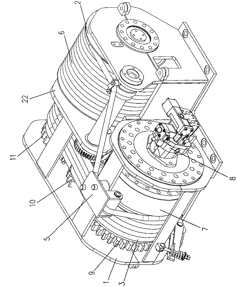
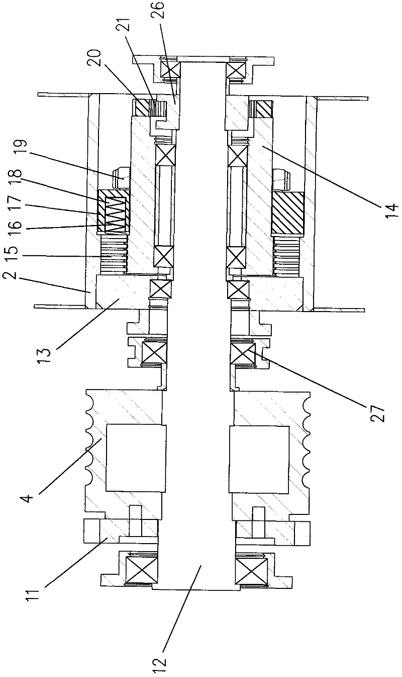
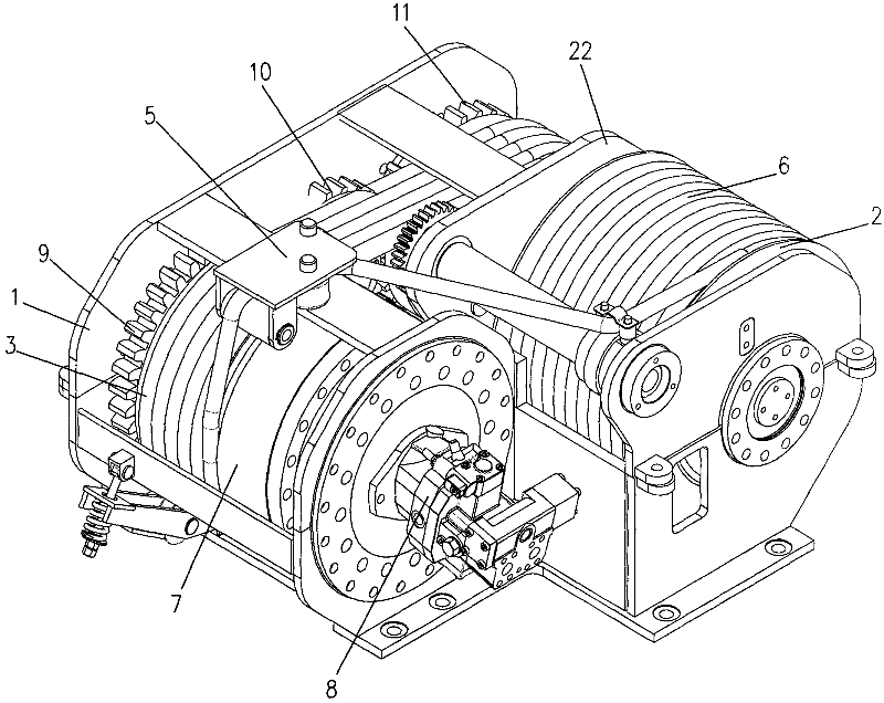
[0012] Such as figure 1 with figure 2 As shown, the vehicle-mounted constant-tension hydraulic winch of the present invention includes a frame 1, a rope storage drum 2, a rear drum 3, a front drum 4, a rope arranging mechanism 5, and a wire rope 6. One end of the wire rope 6 is fixed on the rope storage drum 2. , The middle section of the wire rope 6 is wound on the rope storage drum 2, the rear drum 3 and the front drum 4 in turn. The right side of the rear of the frame 1 is provided with a reducer 7, the power input shaft of the reducer 7 and the power output of the hydraulic motor 8. The shaft is connected in transmission. The power output shaft of the reducer 7 is connected in transmission with the right end of the rear drum shaft (not shown in the figure). The axis of the rear drum shaft is arranged in the horizontal direction. The rear drum 3 is sleeved and fixed in the middle of the rear drum shaft. The left side of the rear roller shaft is sleeved with a driving gear 9...


PUM


Abstract

The invention relates to a vehicle-mounted constant-tension hydraulic capstan. The vehicle-mounted constant-tension hydraulic capstan comprises a stander, a rope storage roller, a rear roller and a front roller, wherein the right side on the rear part of the stander is provided with a reducer, a power input shaft of the reducer is connected with a power output shaft of a hydraulic motor in a transmission way, a power output shaft of the reducer is connected with the right end of a rear roller shaft in a transmission way, the axis of the rear roller shaft is arranged in the transverse horizontal direction, the rear roller is fixedly sleeved on the middle part of the rear roller shaft, a driving gear is sleeved on the left side of the rear roller shaft, the left end of the rear roller shaft is rotatably installed on the stander, the driving gear is engaged with a reversing gear, the reversing gear is fixedly sleeved on a reversing shaft, two ends of the reversing shaft are rotatably installed on the stander, the reversing gear is engaged with a driven gear, the driven gear is fixedly sleeved on the left side of a front roller shaft, and two ends of the front roller shaft are rotatably installed on the stander. The invention aims at providing the vehicle-mounted constant-tension hydraulic capstan with a compact structure, stable traction torque, reliable working performance and an overloading protection function.

Description

Technical field [0001] The invention relates to a vehicle-mounted constant-tension hydraulic winch. Background technique [0002] The vehicle-mounted winch can be installed on military rescue vehicles, rescue vehicles, trailers and various engineering vehicles, and can also be installed on police or civilian wreckers, trailers, engineering vehicles and engineering machinery for overturning , Rollover, ditch, siltation and loss of the ability to carry out rescue operations, can also be used to self-rescue the vehicle. The existing vehicle-mounted winch is composed of a bracket, a front drum, a rear drum, a rope storage drum, a steel wire rope, a speed reduction mechanism, a transmission mechanism, and a rope arrangement mechanism. When the winch is carrying out the rope-rewinding work, the rope arranging mechanism guides the steel wire rope to be wound on the rope storage drum in layers; when the winch is carrying out the rope laying work, the rope arranging mechanism guides the ...

Claims


Application Information

Patent Timeline
IPC IPC(8): B66D1/26B66D1/36B66D1/08
Inventor 贾小平张国纲李晓明于魁龙王明强迟锐汤良道杨静波李炯邓炯南刘宇明
Owner ACADEMY OF ARMORED FORCES ENG PLA
Why Eureka
Try Eureka