Separating shunt suction drainage water-free sweeping vehicle

A road sweeper and car body technology, which is applied in road cleaning, construction, cleaning methods, etc., can solve the problems of short service life of mechanical tools, narrow use range, complex mechanical structure, etc., and achieve energy saving, simple structure, and cleaning powerful effect

Inactive Publication Date: 2012-08-22
YANTAI TONGTIANDA BLOWER MFG CO LTD
View PDF7 Cites 10 Cited by
  • Summary
  • Abstract
  • Description
  • Claims
  • Application Information

AI Technical Summary

Problems solved by technology

[0002] All kinds of environmental sanitation machinery and tools such as road sweepers, sweepers and vacuum cleaners that people use now use the working principle of vacuum filtration to suck dust, garbage and waste. The suction effect is poor, the noise is loud, and the service life of the machinery and tools is short, especially The environmental sanitation road sweeper adopts the suction-sweeping composite working principle, and needs to add a sweeping brush, water pump, water tank and its power device, resulting in complex mechanical structure, high cost, high energy consumption, and low efficiency, and is not suitable for use in icy areas in winter. Narrow range of use

Method used


Image

  • Separating shunt suction drainage water-free sweeping vehicle
  • Separating shunt suction drainage water-free sweeping vehicle
  • Separating shunt suction drainage water-free sweeping vehicle

Examples


Embodiment 1

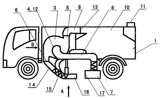
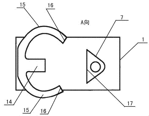
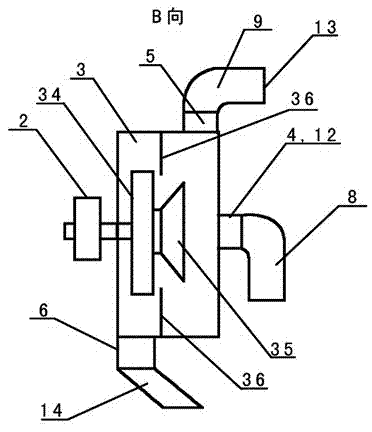
[0046] Embodiment 1, reference figure 1 , figure 2 , image 3 , Separation and diversion suction and exhaust waterless road sweeper, including car body 1, power system (pulley) 2, separation and diversion suction and exhaust fan 3, separation and diversion suction and exhaust fan impeller 34, front isolation shunt 35 of the suction and exhaust fan impeller, and inner barrier of the suction and exhaust fan Separator 36, air inlet of separation and diversion suction and exhaust fan 4, discharge port of separation and diversion suction and exhaust fan 5, exhaust port of separation and diversion suction and exhaust fan 6, garbage suction nozzle 7, garbage suction pipe 8, garbage conveying pipe 9, garbage container 10 , Garbage container air outlet 11. The garbage suction nozzle 7 is connected with the garbage suction pipe 8, the garbage suction pipe outlet 12 is connected with the air inlet 4 of the separation and diversion suction and exhaust fan, the inlet of the garbage deli...

Embodiment 2

[0050] Embodiment 2, refer to Figure 4 , Figure 5 , this example is basically the same as Example 1, and the difference is that the garbage suction pipe 8 is provided with a garbage suction branch pipe 18 connected to the garbage suction pipe downstream, and the garbage suction branch pipe 18 is located at the bottom wall of the car body, and the garbage suction The branch pipe inlet 19 points to the outer space at the bottom of the car body, and the garbage suction branch pipe inlet 19 is a bell mouth type.

[0051] During work, when the garbage cleaning nozzle blows the garbage, there will be mud and dust flying in the outer space of the bottom of the car body. Since there are garbage suction branch pipes and garbage suction branch pipe inlets, the garbage cleaning nozzle blows the mud and dust flying up from the garbage. The dust can be sucked clean by the inlet of the garbage suction branch pipe and the garbage suction branch pipe at any time, and then input into the ga...

Embodiment 3

[0053] Embodiment 3, refer to Figure 6 , Figure 7 , this example is basically the same as Example 1, the difference is that this example is provided with an auxiliary blower fan 20 --- a suction and discharge material backflow fan, the outside of the auxiliary blower fan air inlet is provided with an auxiliary blower blower inlet pipe 21, and the auxiliary blower blower inlet pipe inlet stretches into The outer space of the bottom wall of the car body; the auxiliary fan exhaust pipe 22 is arranged outside the auxiliary fan exhaust port, and the outlet of the auxiliary fan exhaust pipe 22 is communicated with the garbage container 10 . The second difference is that the outer side of the car body bottom wall in this example is provided with a dust collection cover 23, the dust collection cover outlet 24 communicates with the inlet of the auxiliary fan air inlet pipe 21, and the dust collection cover inlet 25 points to the car body bottom wall from top to bottom. outer space. ...


PUM


Abstract

The invention discloses a separating shunt suction drainage water-free sweeping vehicle. The separating shunt suction drainage water-free sweeping vehicle comprises a vehicle body, a power system, a separating shunt suction drainage fan, a separating shunt suction drainage fan air inlet, a separating shunt suction drainage fan discharge outlet, a separating shunt suction drainage fan air exhaust outlet, a garbage suction nozzle, a garbage suction pipe, a garbage delivery pipe and a garbage container, and is characterized in that a suction drainage fan air exhaust pipe is arranged at the outer side of the separating shunt suction drainage fan air exhaust outlet and stretches to the bottom part of the vehicle body, the tail end of the suction drainage fan air exhaust pipe is provided with suction drainage fan air exhaust branch pipes which are in bilateral symmetrical arrangement and are respectively positioned at the left side and the right side of the bottom part of the vehicle body, the tail ends of the suction drainage fan air exhaust branch pipes are provided with air exhaust branch pipe garbage sweeping nozzles, and the air exhaust branch pipe garbage sweeping nozzles point to a garbage suction nozzle inlet which is arranged between the bottom part of the vehicle body and the ground from two sides of the bottom part of the vehicle body. According to the separating shunt suction drainage water-free sweeping vehicle disclosed by the invention, by adopting the new working principle for cleaning garbage and rubbish, the cleaning effect is good, the energy consumption is less, the efficiency is high, the function is multiple, the use range is wide, the manufacturing cost is low, and the maintenance is convenient.

Description

technical field [0001] The invention relates to a waterless road sweeper for separation, diversion, suction and discharge, and belongs to the technical field of sanitation engineering machinery. Background technique [0002] All kinds of environmental sanitation machinery and tools such as road sweepers, sweepers and vacuum cleaners that people use now use the working principle of vacuum filtration to suck dust, garbage and waste. The suction effect is poor, the noise is loud, and the service life of the machinery and tools is short, especially The environmental sanitation road sweeper adopts the suction-sweeping composite working principle, and needs to add a sweeping brush, water pump, water tank and its power device, resulting in complex mechanical structure, high cost, high energy consumption, and low efficiency, and is not suitable for use in icy areas in winter. The scope of use is narrow. Contents of the invention [0003] The purpose of the present invention is t...

Claims


Application Information

Patent Timeline
Patent Type & Authority Applications(China)
IPC IPC(8): E01H1/08
Inventor 林钧浩
Owner YANTAI TONGTIANDA BLOWER MFG CO LTD
Why Eureka
Try Eureka