Pneumatic-electric-control volume-variable type amount of liquid control device

A technology for volume control and control device, which is applied in the direction of using electric device flow control, infusion set, enema/irrigator, etc., can solve the problem of inaccurate measurement and control, inability to separate liquid and gas, and affect the accuracy of measurement and control. and other problems, to achieve the effect of improving gas tightness, ensuring smooth operation and reliability, and good sealing effect

Active Publication Date: 2014-07-02
TONGYE TECH DEV
View PDF6 Cites 0 Cited by
  • Summary
  • Abstract
  • Description
  • Claims
  • Application Information

AI Technical Summary

Problems solved by technology

However, in specific work, especially in the medical field, the body fluid flowing through the liquid volume control device often contains some solid dirt, which affects the accuracy of measurement and control
Non-contact flow control devices, such as ultrasonic sensors or infrared sensors, cannot achieve the separation of liquid and gas in the measured space when they are working, and are easily caused by the presence of water vapor in the measured space or even on the probe, or the presence of air pockets in the liquid. , resulting in inaccurate measurement and control

Method used


Image

  • Pneumatic-electric-control volume-variable type amount of liquid control device
  • Pneumatic-electric-control volume-variable type amount of liquid control device
  • Pneumatic-electric-control volume-variable type amount of liquid control device

Examples


Embodiment Construction

[0024] The present invention will be further described in detail below through the specific examples, the following examples are only descriptive, not restrictive, and cannot limit the protection scope of the present invention with this.

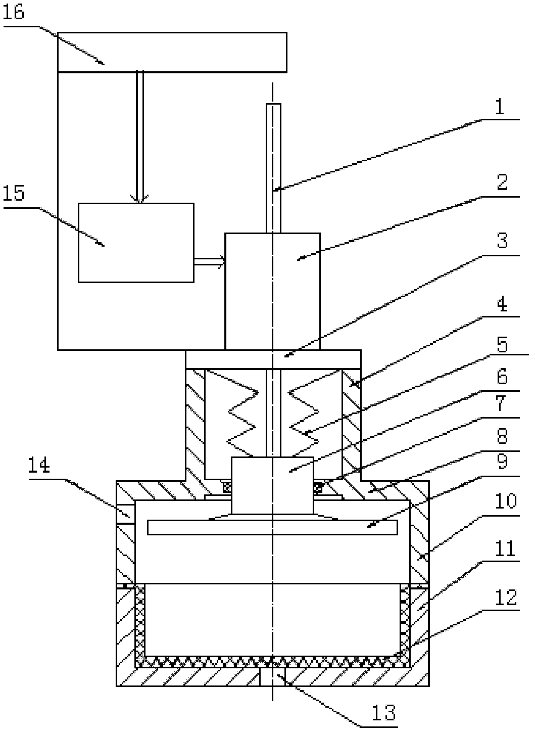
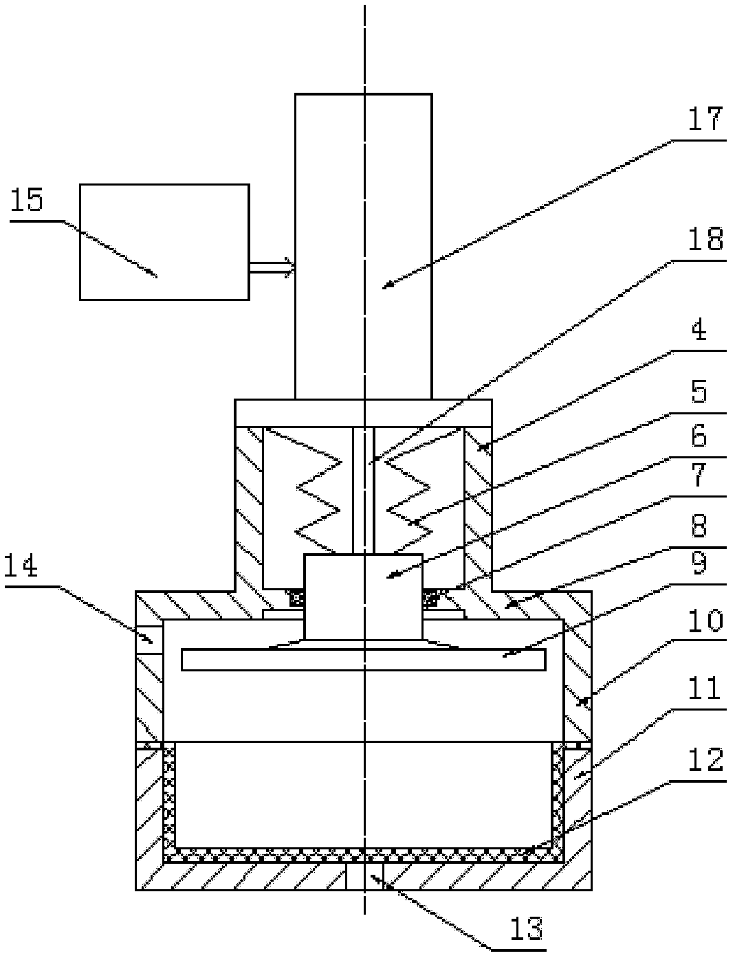
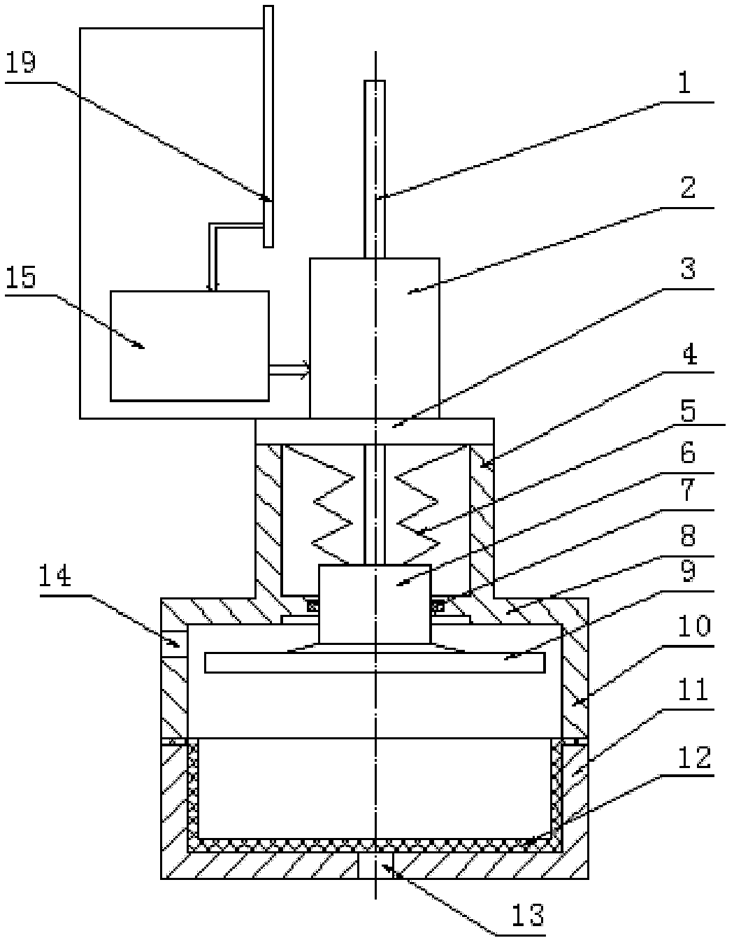
[0025] A gas-electric control volume variable liquid volume control device, which is mainly composed of a tank body, an isolation membrane 12, an adjustment plate 9, a lifting drive mechanism, a control unit and a sealing unit, and the tank body is composed of a lower tank body 11 and an upper tank body 10 and an upper support box 4, an isolation film is installed between the lower tank body and the upper tank body, a support box is formed on the upper part of the lower tank body, a liquid inlet and outlet 13 is formed on the bottom surface of the lower tank body, and an air control valve is formed on the side wall of the upper tank body Interface 14; the adjustment disc is installed horizontally in the upper tank body, the disc seat 6 made o...


PUM


Abstract

The invention relates to a pneumatic-electric-control volume-variable type amount of liquid control device, which mainly comprises a can body, an isolating membrane, an adjusting disc, a lifting drive mechanism, a control unit and a sealing unit, wherein the can body comprises a lower can body, an upper can body and an upper supporting box, and the isolating membrane is installed between the lower can body and the upper can body; the upper part of the upper can body is provided with the supporting box, and the bottom surface of the lower can body is provided with a liquid inlet and outlet; the side wall of the upper can body is provided with a pneumatic control interface, and the adjusting disc is horizontally installed in the upper can body; a disc seat arranged at the top surface of the adjusting disc is movably installed on the top surface of the upper can body, and the sealing unit is installed between the disc seat at the top surface of the adjusting disc and the top surface of the upper can body; and the lifting drive mechanism is fixedly installed at the upper part of the supporting box, and the lower end of a lifting drive rod of the lifting drive mechanism extends into the inner part of the supplying box and is fixedly installed at the disc seat at the top surface of the adjusting disc; and the lifting drive mechanism is electrically connected with the control unit. The device realizes amount of liquid control by adopting volume regulation and controls liquid flow by adopting positive / negative pressure transformation, and the device has the advantages of accurate control, simpleness and convenience in operation and wide range of application.

Description

technical field [0001] The invention relates to a liquid volume control device, in particular to a gas-electric control volume variable type liquid volume control device. Background technique [0002] In the fields of medical treatment and chemical industry, it is often necessary to control the liquid volume. Existing fluid control devices include contact and non-contact. Contact liquid volume control devices, such as flow sensors, require that the liquid passing through the sensor must be free of solid impurities in order to achieve more accurate control. However, in specific work, especially in the medical field, the body fluid flowing through the liquid volume control device often contains some solid dirt, which affects the accuracy of measurement and control. Non-contact flow control devices, such as ultrasonic sensors or infrared sensors, cannot achieve the separation of liquid and gas in the measured space when they are working, and are easily caused by the presence ...

Claims


Application Information

Patent Timeline
Patent Type & Authority Patents(China)
IPC IPC(8): G05D7/06A61M3/02
Inventor 翟贵生李凤林殷华于春泳李会战
Owner TONGYE TECH DEV
Why Eureka
Try Eureka