AI technical title is built by Patsnap AI team. It summarizes the technical point description of the patent document.
A vacuum processing device and plate technology, applied in the direction of plasma, coating, gaseous chemical plating, etc., to achieve the effect of improving gas tightness, eliminating problems, and preventing component deformation
Pending Publication Date: 2021-08-13
ULVAC INC
View PDF2 Cites 0 Cited by
Summary
Abstract
Description
Claims
Application Information
AI Technical Summary
This helps you quickly interpret patents by identifying the three key elements:
Problems solved by technology
Method used
Benefits of technology
Problems solved by technology
[0018] 2. Provide a treatment device that solves the problems caused by the thermal expansion and contraction of large-area shower plates
Method used
Image
Click on the blue label to locate the original text in one second.
Reading with bidirectional positioning of images and text.
Examples
experiment example 1
[0282] In the vacuum processing apparatus 100 of the above-mentioned embodiment, the formation of an oxide film has been studied, and in particular, the formation of an SiO film using TEOS (tetraethoxysilane) with a large molecular weight as a source gas has been studied. X film forming.
[0283] The following shows TEOS-SiO X Items in the film-forming process.
[0290] ·Height dimension of electrode frame 110: 32.5mm
[0291] ·Thickness dimension of the longitudinal plate surface 113: 3mm
[0292] Figure 9 The simulation results of the temperature distribution in the shower plate are shown.
[0293] exist Figure 9 , one quarter of the shower plate is sho...
experiment example 2
[0296] As in Experimental Example 1, SiO was investigated using TEOS (tetraethoxysilane). X film forming.
[0297] Here, the width dimension is the same, but the device has an electrode frame with a dense block structure in which the sliding plate and the electrode frame in the above embodiment are integrally formed without grooves and spaces.
[0298] Figure 10 The simulation results of the temperature distribution in the shower plate are shown.
[0299] exist Figure 10 , one quarter of the shower plate is shown. That is, the lower left is the central position of the shower plate.
[0300] From this result, in the vacuum processing apparatus in Experimental Example 2, the highest temperature in the shower plate was 423.15°C, the lowest temperature was 338.16°C, and the in-plane temperature distribution Δ=84.99°C.
[0301] Furthermore, it can be seen that by improving the in-plane temperature distribution of the shower plate 105, the stress distribution in SiN can be im...
PUM
Abstract
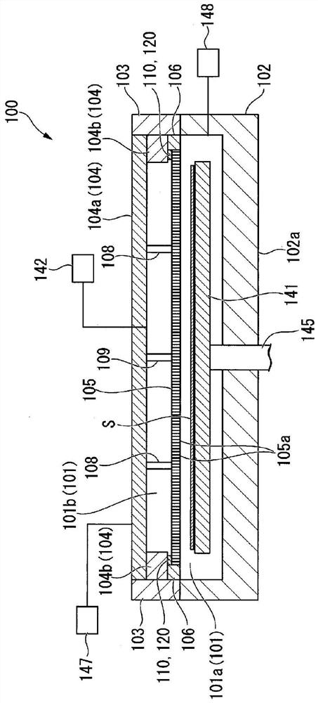
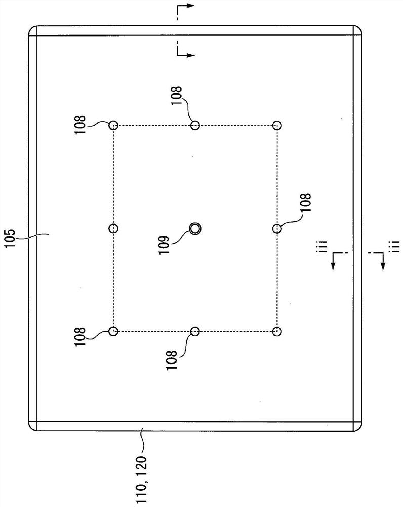
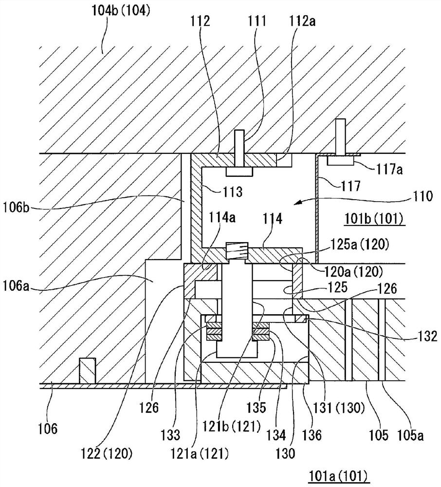
This vacuum processing device performs plasmaprocessing. The vacuum processing device has: an electrodeflange connected to a high-frequency power supply; a shower plate that is set apart from and faces the electrodeflange, the shower plate serving as a cathode together with the electrodeflange; an insulation shield provided around the shower plate; a processing chamber in which a substrate being processed is disposed on the side of the shower plate that is opposite from the electrode flange; an electrode frame attached to the shower-plate side of the electrode flange; and a slide plate attached to the peripheral edge part, on the electrode-frame side, of the shower plate. The shower plate is formed so as to have a substantially rectangular outline. The electrode frame and the slide plate can be made to slide in correspondence with thermal deformation occurring when the temperature of the shower plate increases or decreases, and the space surrounded by the shower plate, the electrode flange, and the electrode frame can be sealed. The electrode frame has: a frame-shaped upper plate surface section attached to the electrode flange; a vertical plate surface section provided upright toward the shower plate from the entire periphery of the outside of the outline of the upper plate surface section; and a lower plate surface section extending, substantially parallel to the upper plate surface section, from the lower end of the vertical plate surface section toward the inside edge of the outline of the upper plate surface section.
Description
technical field [0001] The present invention relates to a vacuum processing apparatus, and particularly to a technology suitable for use in processing with plasma. [0002] This application claims priority based on Japanese Patent Application No. 2019-000528 filed in Japan on January 7, 2019, and the contents thereof are incorporated herein. Background technique [0003] Conventionally, a plasma processing apparatus is known that performs film formation, in particular plasma CVD (Chemical Vapor Deposition) or etching, or other surface treatment of a substrate as a treatment using plasma. In this plasma processing apparatus, in order to have a film forming space (reaction chamber), the processing chamber is constituted by insulating flanges sandwiched between the chamber and electrode flanges. In the processing chamber, a shower electrode plate connected to the electrode flange and having a plurality of ejection ports and a heater for the substrate to be arranged are arrange...
Claims
Application Information
Patent Timeline
Application Date:The date an application was filed.
Publication Date:The date a patent or application was officially published.
First Publication Date:The earliest publication date of a patent with the same application number.
Issue Date:Publication date of the patent grant document.
PCT Entry Date:The Entry date of PCT National Phase.
Estimated Expiry Date:The statutory expiry date of a patent right according to the Patent Law, and it is the longest term of protection that the patent right can achieve without the termination of the patent right due to other reasons(Term extension factor has been taken into account ).
Invalid Date:Actual expiry date is based on effective date or publication date of legal transaction data of invalid patent.

