Traveling wave ultrasonic motor similar to the gear transmission and control method thereof

A technology of gear transmission and ultrasonic motor, applied in the direction of generator/motor, piezoelectric effect/electrostrictive or magnetostrictive motor, electrical components, etc., can solve the problem of ultrasonic motor resonance frequency drift, large friction loss, unfavorable ultrasonic Motor stability and long-term problems, to achieve the effect of improving transmission efficiency

Active Publication Date: 2012-08-22
SHANGHAI JIAO TONG UNIV
View PDF5 Cites 19 Cited by
  • Summary
  • Abstract
  • Description
  • Claims
  • Application Information

AI Technical Summary

Problems solved by technology

However, since the stator of the existing ultrasonic motor only vibrates at the micron level in the ultrasonic frequency band, this driving method only utilizes the frictional driving force of the traveling wave at the peak, resulting in low mechanical efficiency and large friction loss
At the same time, the heat generated by friction will cause the resonance frequency of the ultrasonic motor to drift, which is not conducive to the stability and long-term output of the ultrasonic motor

Method used


Image

  • Traveling wave ultrasonic motor similar to the gear transmission and control method thereof
  • Traveling wave ultrasonic motor similar to the gear transmission and control method thereof
  • Traveling wave ultrasonic motor similar to the gear transmission and control method thereof

Examples


Embodiment Construction

[0025] The idea, specific structure and technical effects of the present invention will be further described below in conjunction with the accompanying drawings, so as to fully understand the purpose, features and effects of the present invention.

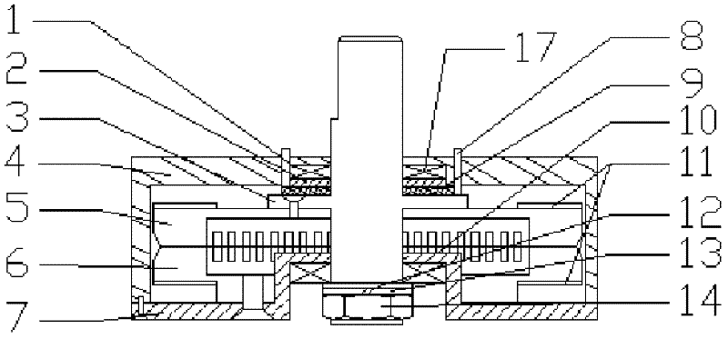
[0026] Such as figure 1 As shown, the gear transmission traveling wave ultrasonic motor of the present invention consists of a first brush 1, a first copper ring 2, a motor output shaft 3, a casing 4, a rotor 5, a stator 6, a base 7, a second brush 8, The second copper ring 9, base bearing 10, pressure sensor 12, elastic washer 13, preload nut 14, housing bearing 17 and other components are composed.

[0027] Wherein, the stator 6 includes a metal elastic body, an annular piezoelectric ceramic 11 and two semi-annular silver-plated electrodes 15 and 16 . Wherein, the annular piezoelectric ceramic 11 is pasted on the lower surface of the metal elastic body. The annular piezoelectric ceramic 11 is evenly partitioned into 16 parts an...


PUM


Abstract

The invention discloses a similar gear transmission travelling wave ultrasonic motor and a control method of the travelling wave ultrasonic motor. The travelling wave ultrasonic motor similar to the gear transmission comprises a first electric brush, a first copper ring, a motor output shaft, a shell, a rotor, a stator, a base, a second electric brush, a second copper ring, a base bearing, a pressure sensor, an elastic washer, a pre-tightening screw nut and a shell bearing. According to the travelling wave ultrasonic motor similar to the gear transmission disclosed by the invention, excitation signals are respectively applied on a stator and a rotor of the ultrasonic motor, two rows of travelling waves are excited in a metal elastic body of the stator and the rotor, and the wave crests and the wave troughs of the two rows of the waves are engaged with each other to form a similar gear transmission, so that the driving of mass points on the surfaces of the stator and the rotor are utilized fully, and the transmission efficiency is improved; and meanwhile, the electric brushes are adopted for supplying power to the rotor of the ultrasonic motor, and the durable and stable running of the ultrasonic motor is guaranteed effectively.

Description

technical field [0001] The present invention relates to an ultrasonic motor and a control method thereof, in particular to a gear-driven traveling wave ultrasonic motor and a control method thereof. Background technique [0002] Ultrasonic motor is a brand-new micro-motor developed in the 1980s. It uses the inverse piezoelectric effect of piezoelectric materials to excite stator piezoelectric ceramics to vibrate in the ultrasonic frequency range through excitation signals, and through the vibration of stator surface particles The elliptical motion rubs against the rotor, thereby converting the microscopic vibration of the surface particles of the stator into the macroscopic rotation of the rotor. Ultrasonic motors are widely used in precision instruments, micro-robots, aerospace and other fields due to their significant advantages such as large torque, no noise, fast response speed, and no electromagnetic interference. [0003] The ultrasonic motor itself is an electromecha...

Claims


Application Information

Patent Timeline
Patent Type & Authority Applications(China)
IPC IPC(8): H02N2/16H02N2/14
Inventor 杨明徐亮庄晓奇叶林
Owner SHANGHAI JIAO TONG UNIV
Why Eureka
Try Eureka