
Punching device of decoration strip products

A decorative strip and product technology, which is applied in metal processing and other directions, can solve the problems of multiple times of taking and taking off products, troublesome processing of porous punching, and difficulty in guaranteeing processing accuracy, so as to reduce labor intensity, reduce production costs, and improve production. efficiency effect

Active Publication Date: 2012-08-29
NINGBO XINTAI MACHINERY
View PDF9 Cites 7 Cited by
  • Summary
  • Abstract
  • Description
  • Claims
  • Application Information

AI Technical Summary

Problems solved by technology

[0002] For the processing of some long and curved parts, such as thin-walled bright surfaces on vehicles, long and curved decorative strips, and complex cross-sections, porous punching processing is required. The porous punching processing of this product is usually It is more troublesome, and the machining accuracy is difficult to guarantee
There are two methods generally used now: 1) Die-cutting in sections, this processing method requires the preparation of multiple dies, and the product needs to be assembled and disassembled many times before it can be completed; and the position of the product will directly affect the Precision
2) On the machining center, milling out in segments, this method also has the problem that the product needs to be taken up and down multiple times, and the machining accuracy is affected
And the above two methods all have the problem of low efficiency

Method used


Image

  • Punching device of decoration strip products
  • Punching device of decoration strip products
  • Punching device of decoration strip products

Examples


Embodiment Construction

[0025] The present invention will be further described in detail below in conjunction with the accompanying drawings and embodiments.

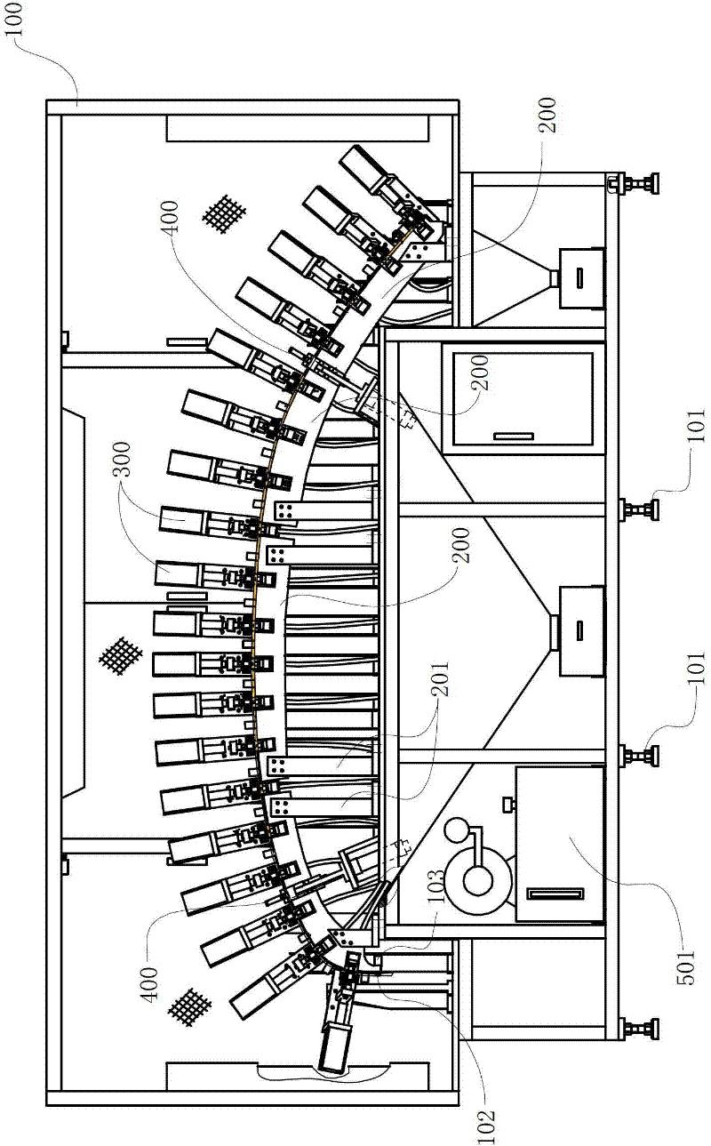
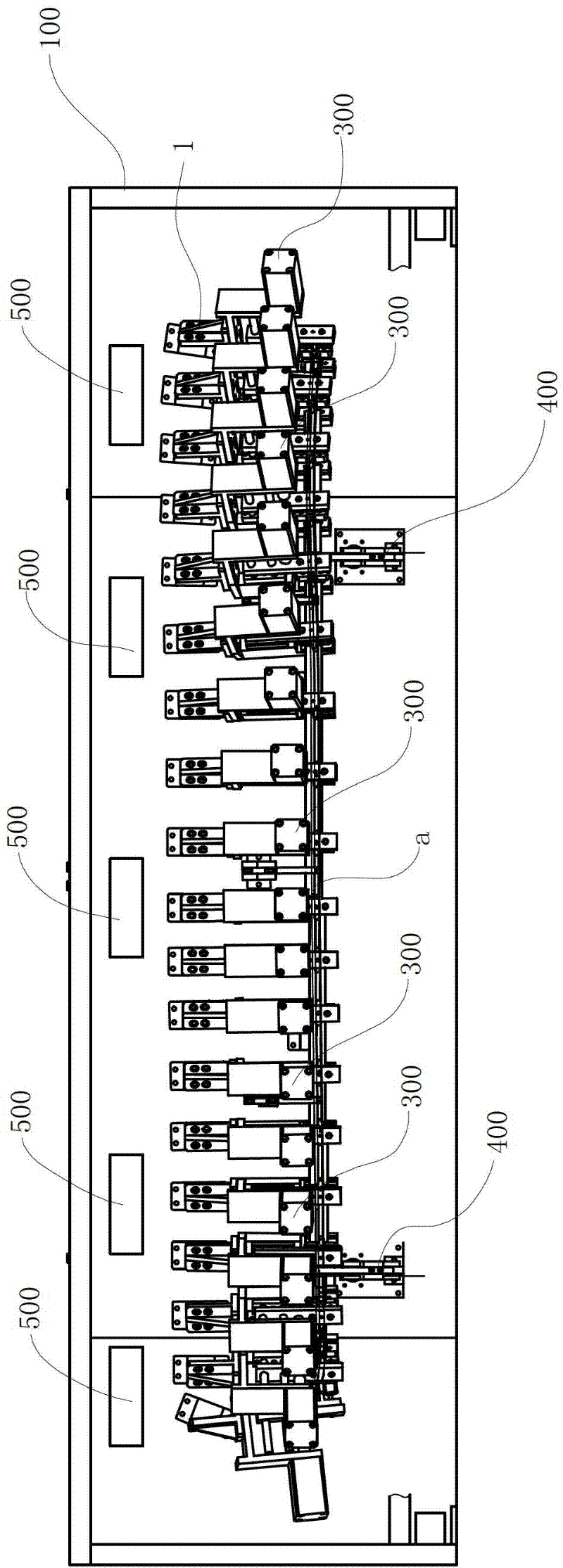
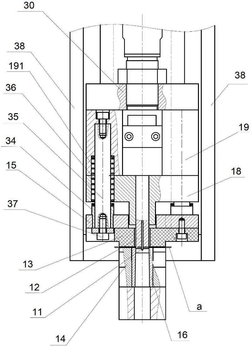
[0026] Punching device of the present invention, as Figure 1-2 As shown, it includes a frame 100, and a plurality of adjustable feet 101 located below the frame 100 can make the frame stable and avoid shaking due to uneven ground. The frame 100 is provided with a plurality of positioning seats separated in turn to form a long positioning seat 200 for placing the workpiece a to be processed when punching. In this embodiment, the spliced ​​positioning seats have a certain radian. To match the workpiece a to be processed, the positioning seat 200 is fixed on the frame 100 through a plurality of vertical positioning seat brackets 201, and on the frame 100 along the length direction of the positioning seat 200, a plurality of The punching assembly 300, and the positioning seat 200 is provided with a plurality of grooves for inserting the die hold...


PUM


Abstract

The invention discloses a punching device of decoration strip products. A strip positioning base which is formed by a plurality of positioning blocks sequentially arranged at intervals and used for laying a work piece to be machined during punching is arranged on a frame; a plurality of punching components are sequentially fixed on the frame at intervals along the length direction of the positioning base; a plurality of grooves for female die seats of the punching components to be inserted into are formed on the positioning base; the height of the plane of the positioning base used for laying the work piece to be machined is level with the height of the female die seats; and simultaneously a discharging component which can discharge a machined work piece from one side of the positioning base and a guiding component which is positioned on the other side of the positioning base and used for laying the work piece to be machined before being punched are also arranged on the frame. The punching device can clamp the strip work piece and punch different positions on the work piece in sequence, is not required to perform multiple position adjustment on the strip work piece, also has the automation and manual combined discharging component, not only improves the operating efficiency and reduces the labor intensity, but also guarantees the safety in production and improves the machining accuracy.

Description

technical field [0001] The invention relates to a punching device, in particular to a punching device for decorative strip products on vehicles. Background technique [0002] For the processing of some long and curved parts, such as thin-walled bright surfaces on vehicles, long and curved decorative strips, and complex cross-sections, porous punching processing is required. The porous punching processing of this product is usually It is troublesome, and the machining accuracy is difficult to guarantee. There are two methods generally used now: 1) Die-cutting in sections, this processing method requires the preparation of multiple dies, and the product needs to be assembled and disassembled many times before it can be completed; and the position of the product will directly affect the Precision. 2) On the machining center, segmental milling, this method also has the problem that the product needs to be taken up and down many times, and the machining accuracy is affected. A...

Claims


Application Information

Patent Timeline
IPC IPC(8): B26F1/38B26F1/44B26D7/01B26D5/12B26D7/18B26D7/06
Inventor 胡剑英
Owner NINGBO XINTAI MACHINERY
Learn More