
Concrete prefabrication member bottler

A technology of concrete prefabricated parts and pouring machines, which is applied in the direction of manufacturing tools, ceramic forming machines, reinforced molding, etc. It can solve the problems of affecting the roundness of the mold, affecting the roundness of the pipe pile, and large physical exertion, so as to enhance the precision of the mold and prolong the life of the mold. The effect of improving the service life and labor efficiency

Inactive Publication Date: 2012-08-29
沈阳市振兴建材实业有限公司
View PDF5 Cites 2 Cited by
  • Summary
  • Abstract
  • Description
  • Claims
  • Application Information

AI Technical Summary

Problems solved by technology

[0005] It has many disadvantages. First, the concrete material is mixed by a large mixer. The ingredients of the material are water, cement, gravel, river sand and admixtures. The accuracy is even calculated in tens of kilograms. It is difficult to control the dryness and accuracy of the material within the specified time for a long time and in batches.
This creates troubles for the workers to operate. The material is dry and sticky, which consumes a lot of energy when working, and the feeding is not full; It can't be molded for hours, even if it is molded, it will greatly affect the quality of the product
In addition, because cement mortar is easy to remain between the upper and lower mold covers, the mortar will accumulate thicker and thicker over time, affecting the roundness of the mold, that is, affecting the roundness of the pipe pile, causing pile loss during the construction process, and also affecting the mold itself. The lifetime of related equipment including
[0006] The second is that there is a large demand for personnel, because the accuracy of materials is not easy to control, so we can only increase the number of personnel to ensure the production speed, but this increases the demand for skilled workers in the production process
Not only does it reduce the labor productivity of production, but it also increases the human factors of product production, resulting in unstable product quality.
It also increases security risks

Method used


Image

  • Concrete prefabrication member bottler
  • Concrete prefabrication member bottler

Examples


Embodiment Construction

[0018] Next, the concrete prefabricated pouring machine of the present invention will be described in detail with reference to the accompanying drawings.

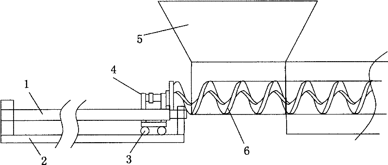
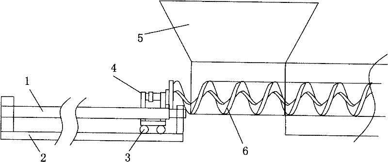
[0019] Prefabricated concrete pouring machine, its structure includes a hopper 5 and a propelling pouring mechanism under the hopper; the propelling pouring mechanism consists of a spiral blade 6 placed in the pouring pipeline and a drive connected to the rear end of the spiral blade to drive the spiral blade to move back and forth Organization 4 constitutes. The driving mechanism connecting the helical blades is placed on the traveling trolley 3 below, and the traveling trolley moves back and forth on the guide rail 2 . An idler roller 1 is arranged on the guide rail, and the traveling trolley drives the driving mechanism and the helical blade to move back and forth on the guide rail along the guide rail which is stable on the idler roller.

[0020] The working principle of the present invention is to put the steel cage i...


PUM


Abstract

The invention discloses a concrete prefabrication member bottler. The concrete prefabrication member bottler structurally comprises a hopper and a boosting and pouring mechanism below the hopper, wherein the boosting and pouring mechanism comprises a spiral vane arranged in a pouring pipeline and a driving mechanism connected to the rear end of the spiral vane for driving the spiral vane to move back and forth. The concrete prefabrication member bottler has the work principle that a die is closed after a reinforcement cage is put in an empty die, then, the screw conveyor part of a feeding mechanism is put into the die, and the material is directly conveyed into the die by being conveyed by the spiral conveyor. Because of mechanical conveying, the labor efficiency is improved, and the difficulty caused to worker operation because materials are dry and thin is avoided. Meanwhile, because a die compounding operation is carried out under the empty die state, user conditions for all relevant equipment is relatively better, the service life of the equipment is prolonged, the die precision is enhanced, and the product quality is improved.

Description

technical field [0001] The invention relates to concrete pouring technology, in particular to a concrete prefabricated part pouring machine. Background technique [0002] Pipe pile is a relatively new type of foundation pile, which originated in the southern provinces of my country in the late 1990s and has been extended to the whole country in recent years in this century. The advantages of pipe piles lie in fast production speed, high quality assurance, and increased construction speed, and due to the wide use of new materials including pc steel rods, high-grade cement and admixtures, the use of materials and resources is saved. Reduced energy consumption. Its appearance has greatly changed the demand for new pile foundations in the construction field of our country. [0003] The production of pipe piles is prefabricated in the factory, which is greatly affected by the increasingly tense labor shortage. Due to the shortage of labor force, it not only restricts the improv...

Claims


Application Information

Patent Timeline
IPC IPC(8): B28B21/58B28B21/02
Inventor 许淼淼
Owner 沈阳市振兴建材实业有限公司
Learn More