Power-driven device of concrete pumping equipment and concrete pumping equipment

A concrete pump, power-driven technology, applied in the direction of fluid pressure actuation device, mechanical equipment, pump, etc., can solve problems such as the inability to meet high-pressure and large-displacement concrete pumping equipment

Inactive Publication Date: 2012-08-29
ZOOMLION HEAVY IND CO LTD
View PDF5 Cites 5 Cited by
  • Summary
  • Abstract
  • Description
  • Claims
  • Application Information

AI Technical Summary

Problems solved by technology

However, since the first power source 1 and the second power source 2 cannot work at the same time, it cannot meet the needs of high-pressure and large-displacement concrete pumping equipment

Method used


Image

  • Power-driven device of concrete pumping equipment and concrete pumping equipment
  • Power-driven device of concrete pumping equipment and concrete pumping equipment
  • Power-driven device of concrete pumping equipment and concrete pumping equipment

Examples


Embodiment approach

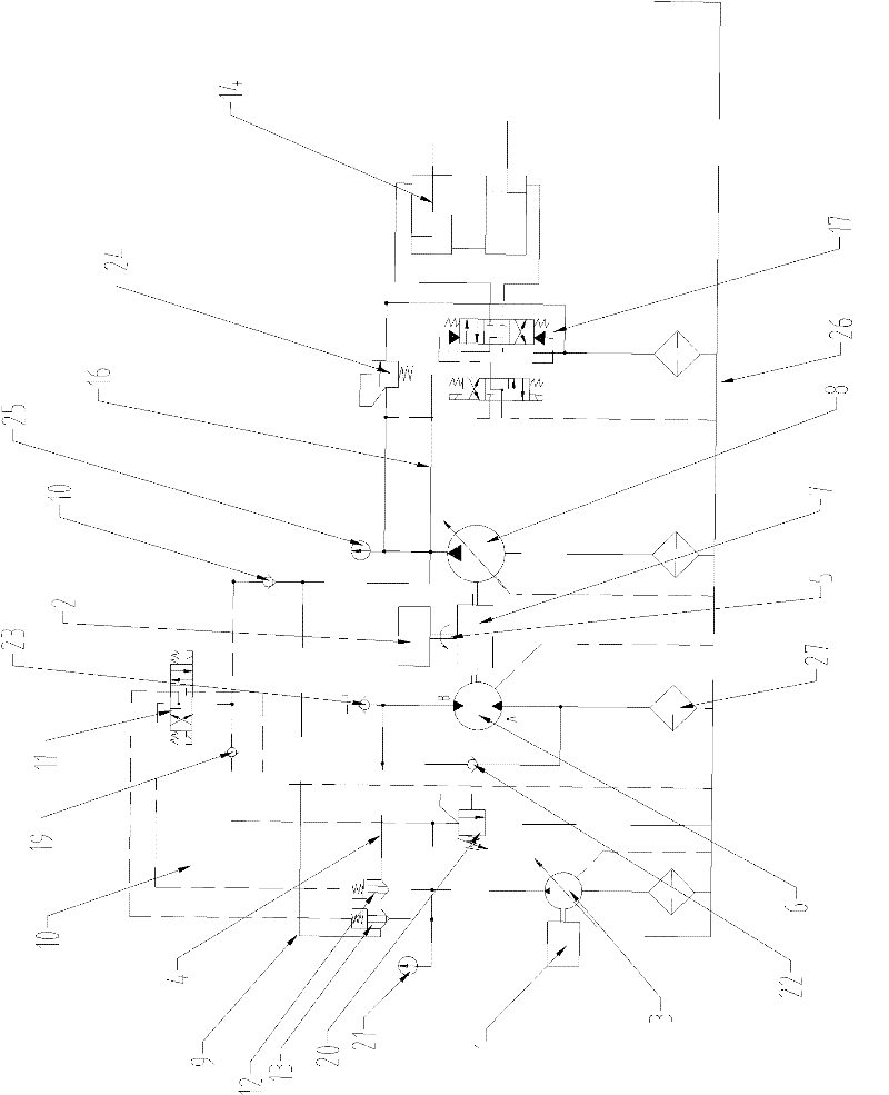
[0031] Such as image 3 As shown, according to an embodiment of the present invention, the hydraulic control element includes a first cartridge valve 12 and a second cartridge valve 13, and the two working oil ports of the first cartridge valve 12 are respectively connected to the The oil outlet of the first hydraulic pump 3 is hydraulically connected to the oil inlet of the hydraulic motor 6, and the two working oil ports of the second cartridge valve 13 are respectively connected to the oil outlet of the first hydraulic pump 3 and the oil inlet of the hydraulic motor 6. The hydraulic drive line 16 is hydraulically connected. In this way, by controlling the opening and closing of the first cartridge valve 12 and the second cartridge valve 13, the on-off of the first hydraulic pipeline 4 and the second hydraulic pipeline 9 can be conveniently controlled, thereby selectively realizing the first The first power output route or the third power output route. This control method ...


PUM


Abstract

The invention provides a power-driven device of concrete pumping equipment, which comprises a first power source (1), a second power source (2), a first hydraulic pump (3), a hydraulic motor (6), a transfer case (7) and a second hydraulic pump (8), wherein the first power source (1) is connected to the first power input end of the transfer case (7) through the first hydraulic pump (3) and the hydraulic motor (6); the second power source (2) is in transmission connected with the second power input end of the transfer case (7); the power output end of the transfer case (7) is in transmission connection with the second hydraulic pump (8); the second hydraulic pump (8) hydraulically drives a workpiece (14) through a hydraulic driving pipeline (16); and the oil outlet of the first hydraulic pump (3) is hydraulically connected to the hydraulic driving pipeline (16). Due to the power-driven device, the pumping property and the working condition adaptive capacity of the concrete pumping equipment can be improved, so as to realize higher economic benefits.

Description

technical field [0001] The invention relates to a power drive device for concrete pumping equipment and concrete pumping equipment including the power drive device. Background technique [0002] CN201386294Y discloses a dual power device for engineering machinery, such as figure 1 As shown, the device includes a first power source 1, a second power source 2, a first hydraulic pump 3, a hydraulic motor 6, a transfer case 7 and a second hydraulic pump 8, and the first power source 1 passes through the first hydraulic pump A hydraulic pump 3 and a hydraulic motor 6 are connected to the first power input end of the transfer case 7, and the second power source 2 is connected to the second power input end of the transfer case 7. The power output end of the moving box 7 is connected to the second hydraulic pump 8 through transmission. The dual power device for construction machinery has two power output routes, the first power output route is: the first power source 1 drives the ...

Claims


Application Information

Patent Timeline
Patent Type & Authority Applications(China)
IPC IPC(8): F15B11/02F15B13/02F04B15/02
CPCF15B11/17F15B2211/20507F15B2211/20576F15B2211/214
Inventor 刘波郭岗裴杰
Owner ZOOMLION HEAVY IND CO LTD
Why Eureka
Try Eureka