
Pressure spring self-locking type power battery quick release device applied to new energy truck

A power battery, self-locking technology, applied in power units, electric power units, battery pack components, etc., can solve problems such as difficulty in maintenance and repair, inability to handle fast, and inability to lock or unlock

Active Publication Date: 2021-03-23
潍柴新能源商用车有限公司
View PDF5 Cites 2 Cited by
  • Summary
  • Abstract
  • Description
  • Claims
  • Application Information

AI Technical Summary

Problems solved by technology

[0003] (1) The lock is not firm and easy to loosen, the power battery body is under too much force, the adaptability to harsh working conditions is poor, and it takes a lot of time to disassemble and assemble
[0004] (2) The cost of automatic interlocking is high, a large number of electrical components are used, the cost and failure rate are high, and maintenance and repair are difficult; firm locking depends on the precise cooperation between parts, requiring precision machining and assembly, or integrated design, which greatly increases vehicle procurement costs
[0005] (2) It does not support manual adjustment of interference lock and lock tightness, and it is easy to loosen when driving for a long time or under severe working conditions and cannot be handled quickly
[0006] (3) No redundancy, delicate parts are vulnerable, making it impossible to lock or unlock
[0007] (3) Customization of power batteries is required, such as size, shape, structure, poor applicability, and cannot be quickly promoted
[0008] (5) Structural mechanics is not considered, which is prone to high stress concentration, resulting in excessive force on the power battery body or damage to the precise structure, and is not suitable for long-term or harsh driving conditions

Method used


Image

  • Pressure spring self-locking type power battery quick release device applied to new energy truck
  • Pressure spring self-locking type power battery quick release device applied to new energy truck
  • Pressure spring self-locking type power battery quick release device applied to new energy truck

Examples


Embodiment 1

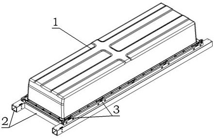
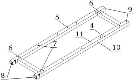
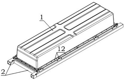
[0052] A pressure spring self-locking power battery quick release device applied to new energy trucks in this embodiment is arranged between the power battery 1 and the battery mounting bracket 2 to realize the connection between the power battery 1 and the battery mounting bracket 2 Quick lock unlock. There are battery installation holes 3 on both sides of the bottom of the power battery 1, through which the battery installation holes 3 are fixedly connected with the battery installation bracket 2; the battery installation bracket 2 is used to carry the power battery, which is composed of two opposite bracket longitudinal The frame structure formed by welding with two opposite bracket beams, the bracket longitudinal beam as the locking beam is called the first locking beam 4 and the second locking beam 5 in this embodiment, the two locking beams and the two bracket beams 6 are all made of square steel pipes, the side of the locking beam in contact with the base of the power b...


PUM


Abstract

The invention relates to a pressure spring self-locking type power battery quick release device applied to a new energy truck, which is arranged between a power battery and a battery mounting bracketand is used for realizing quick locking and unlocking between the power battery and the battery mounting bracket. The device is characterized by structurally comprising two locking beams for forming asupporting part of the battery mounting bracket, and main and auxiliary locks respectively integrated on the two locking beams, the main lock and the auxiliary lock are the same in structural composition and each comprise a locking and unlocking mechanism, a lock row assembly, a spring bolt assembly and an adjustable self-locking mechanism. The device is advantaged in that automatic locking, multi-mode manual adjustment and calibration, associated unlocking, staggered multiple interference fit and firm locking can be achieved, overhauling and maintenance can be rapidly conducted through simple tools, the structural comprehensive strength is high, deformation resistance and cracking resistance are achieved, the fault redundancy is high, working condition adaptability is high, and the equipment adaptation degree is high.

Description

technical field [0001] The invention relates to a quick release device for a power battery, in particular to a spring self-locking quick release device for a power battery applied to a new energy truck, and belongs to the technical field of new energy battery structures. Background technique [0002] At present, the power batteries of new energy trucks cannot meet the purpose of being put into operation quickly due to the long charging time, which affects the use value of the vehicles. At present, the quick battery replacement system has begun to be applied to new energy trucks, and power battery quick release devices for new energy trucks with various structures have been developed, but the existing power battery quick release devices generally have the following technical defects: [0003] (1) The lock is not firm and easy to loosen, the power battery body is under too much force, the adaptability to harsh working conditions is poor, and it takes a lot of time to disasse...

Claims


Application Information

Patent Timeline
IPC IPC(8): B60S5/06H01M50/249H01M50/258H01M50/244
CPCB60S5/06Y02T10/7072
Inventor 王立坤郑乐堂叶新伟
Owner 潍柴新能源商用车有限公司
Learn More