Electro-wetting display unit and electro-wetting display system

An electrowetting display and electrode technology, applied in the direction of optical components, optics, instruments, etc., can solve the problems of reducing the contrast and transmittance of the display, affecting the display effect, and occupying non-polar fluids

Active Publication Date: 2012-08-29
BOE TECH GRP CO LTD
View PDF6 Cites 17 Cited by
  • Summary
  • Abstract
  • Description
  • Claims
  • Application Information

AI Technical Summary

Problems solved by technology

However, when a voltage is applied between the polar fluid and the lower electrode for bright state display, as Figure 1b , 2b As shown by the arrows in and 3b, the non-polar fluid shrinks, but it still remains in the corners of the display pixels, making it impossible to achieve a completely uniform display when the bright state is displayed
Especially when it is used for black and white disp

Method used


Image

  • Electro-wetting display unit and electro-wetting display system
  • Electro-wetting display unit and electro-wetting display system
  • Electro-wetting display unit and electro-wetting display system

Examples


Embodiment Construction

[0024] In order to make the content of the present invention clearer and easier to understand, specific embodiments of the present invention will be described in detail below in conjunction with the accompanying drawings.

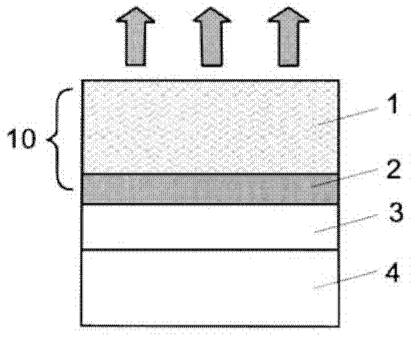
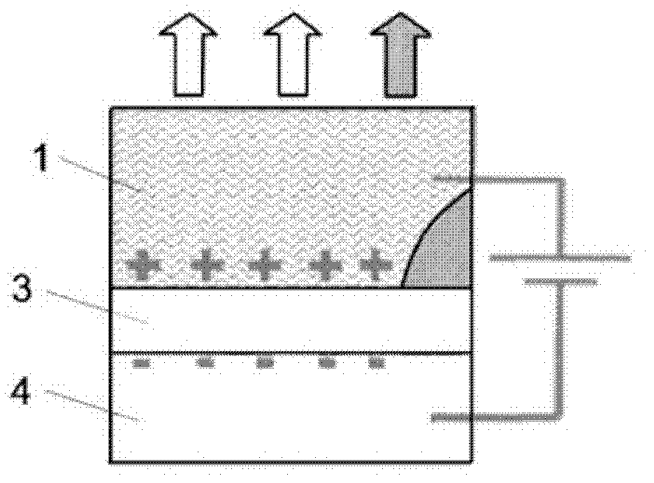
[0025] Figure 1a A cross-sectional view of an electrowetting display unit in the prior art is schematically shown. From Figure 1a It can be seen that the dielectric layer 3 is interposed between the fluid chamber 10 and the electrode 4 , and its contact surface with the non-polar fluid 2 is a flat surface. right Figure 1a When a voltage is applied to the electrowetting cell shown, the contact surface becomes more hydrophilic (wetted), since the previously water-resistant surface now becomes more water-absorbent, the non-polar fluid layer must not move under surface tension. Without changing its existing form, it changes from flat film to the corner of the display unit, such as Figure 1b shown. From Figure 1a and Figure 1b As can be seen from the ar...


PUM


Abstract

The invention provides an electro-wetting display unit and an electro-wetting display system. The electro-wetting display unit comprises a fluid layer, a dielectric layer and an electrode, wherein the fluid cavity comprises polar fluid, colored non-polar fluid and a partition wall used for surrounding the polar fluid and the non-polar fluid; the dielectric layer is positioned below the fluid cavity and is contacted with the non-polar fluid or the polar fluid in the fluid cavity; and the electrode is positioned below the dielectric layer. The electro-wetting display unit is characterized in that a hollow groove is arranged in the partition wall, is provided with an opening facing to the dielectric layer and is used for completely or partly storing the non-polar fluid when the voltage is applied between the polar fluid and the electrode. The electro-wetting display system comprises the electro-wetting display unit. When the electro-wetting display unit trends to be in the bright state in display, and the non-polar fluid paved above the dielectric layer originally enters the hollow groove by the assistance of the extrusion force on the non-polar fluid caused by the polar fluid controlled by the electrode, and is not attached at one corner or the middle area of the bottom surface.

Description

technical field [0001] The present invention relates to the field of display technology, in particular, the present invention relates to an electrowetting (electrowetting) display unit and an electrowetting display system. Background technique [0002] Electrowetting display is a new display technology emerging in recent years. Electrowetting display technology is more and more popular because of its characteristics of bistable display, good reflectivity, low power consumption, wide temperature range and fast enough response speed. Electrowetting display technology is still in its infancy, but its superior performance and development potential indicate that in the field of display technology in the future, electrowetting display will definitely occupy a place and become an important display method. [0003] Electrowetting display technology is a technology that controls the surface layer of the surrounded fluid by controlling the voltage to cause changes in the electrowetti...

Claims


Application Information

Patent Timeline
IPC IPC(8): G02B26/02
CPCG02B26/005
Inventor 田肖雄
Owner BOE TECH GRP CO LTD
Why Eureka
Try Eureka