Method, device and system for establishing and using floating segments

A floating network segment and network technology, applied in the field of communication, can solve problems such as network resource waste, and achieve the effect of alleviating link congestion and reducing waste.

Active Publication Date: 2012-08-29
HUAWEI TECH CO LTD
View PDF2 Cites 9 Cited by
  • Summary
  • Abstract
  • Description
  • Claims
  • Application Information

AI Technical Summary

Problems solved by technology

In this case, resulting in a waste of network resources

Method used


Image

  • Method, device and system for establishing and using floating segments
  • Method, device and system for establishing and using floating segments
  • Method, device and system for establishing and using floating segments

Examples


Embodiment 1

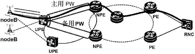
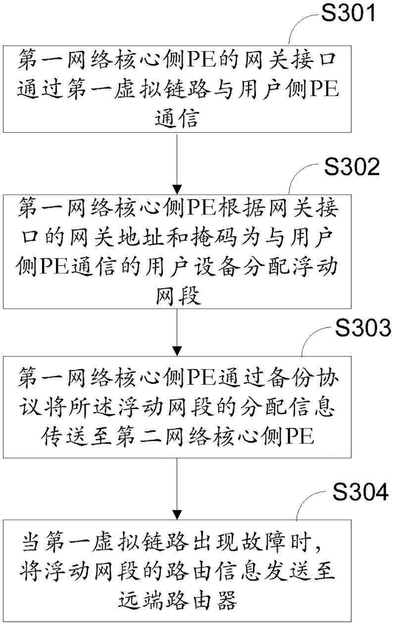
[0028] Such as image 3 As shown, according to an embodiment of the present invention, the method for establishing and using a floating network segment starts at step S301, and the gateway interface of the PE at the core side of the first network (ie, the primary NPE) passes through the first virtual link PW (ie, the primary NPE). Use PW) to connect to corresponding user side PE (UPE). Figure 4 The network schematic diagram of the above-mentioned implementation mode is shown. UPE and NPE form an access network. The active NPE is NPE1, which is the operator's edge router on the core side of the network. It communicates with the operator's edge router on the user side through the active virtual link PW1 The UPE1 communicates, and the UPE1 communicates with the operator edge router NPE2 on the core side of the network through the standby virtual link PW3. Virtual links PW1 and PW3 correspond to floating network segment 1 and floating network segment 2, respectively. The floati...

Embodiment 2

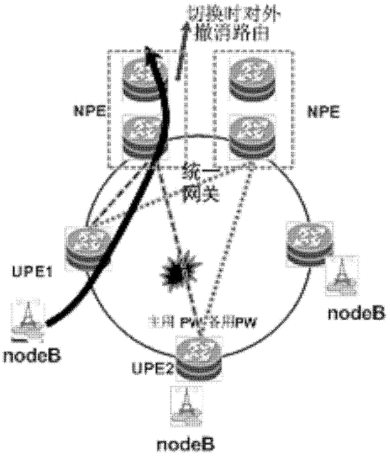
[0051] The application of the floating network segment in the H-VPLS solution is as follows: Figure 9 shown. As shown in the figure, each UPE (903, 904 or 905) and two NPEs (901 and 902) respectively establish an active PW and a standby PW, and the active PW and the standby PW serve as the main NPE and the standby NPE respectively. The spoke PW of the virtual switching instance (VSI), the active NPE and the VSI on the standby NPE are respectively used as gateway interfaces (configure the gateway IP address and mask). If the NPE is two separate devices (such as AGG and NPE, AGG refers to the aggregation device, and the difference from NPE is that AGG is not a layer-3 termination point), where AGG configures VSI and communicates with NPE through a VLAN interface (connected to VSI) Association, the NPE configures the gateway IP and mask on the interface corresponding to the VLAN.

[0052] According to an embodiment of the present invention, according to an embodiment of the pr...

Embodiment 3

[0075] According to an embodiment of the present invention, there is a layer 2 Ethernet network between the UPE and the NPE. For a Layer 2 network, the UPE and NPE are forwarded based on VLANs. The active and standby VLANs are configured between the UPE and the active and standby NPEs. Normally, packets are forwarded from the active An NPE is the primary VLAN, and other VLANs that support multiple different UPEs use another NPE as the primary VLAN, thereby implementing traffic load balancing.

[0076] According to an embodiment of the present invention, the gateway interface is associated with the VLAN: the gateway interface supports simultaneous termination of multiple different VLANs, and the same gateway IP address and network segment mask are configured, and user data of different VLANs can be processed through the gateway interface at the same time.


PUM


Abstract

The invention relates to the field of communication and discloses method, device and system for establishing and using floating segments. Main and standby network core sides PE are established and are respectively connected with a user side PE through main and standby virtual links, and the main network core side PE distributes a floating segment corresponding to the virtual links to user equipment which is communicated with the user side PE. The main network core side PE copies and stores the distributed information of the floating segment into the standby network core side PE. When the main virtual link breaks down, a remote router is communicated with the user equipment through the routes of the standby network core side PE and the floating segment corresponding to the standby virtual link.

Description

technical field [0001] The invention relates to the communication field, in particular to a method, device and system for establishing and using a floating network segment. Background technique [0002] PW (Pseudo wire, virtual link) is a tunnel technology based on IP / MPLS (Multi-Protocol Label Switching, Multi-Protocol Label Switching) network. message) transparently transmitted to the peer. figure 1 What is shown is an existing application scenario carried by IPRAN (Radio Access Network, wireless access network): [0003] Such as figure 1 As shown, UPE (user-end provider edge, operator edge equipment on the user side), NPE (network provider edge, operator edge equipment on the network core side), and PE (provider edge, operator edge equipment) together form an IP RAN bearer network , where the UPE is connected to the base station, and the PE is connected to the RNC (radio network controller, radio network controller). The data of the base station is accessed through the...

Claims


Application Information

Patent Timeline
IPC IPC(8): H04L12/56H04L12/46H04L29/12H04L45/16
CPCH04L45/22H04L45/28
Inventor 滕新东
Owner HUAWEI TECH CO LTD
Why Eureka
Try Eureka