All steel clothing

A technology for metal card clothing and card clothing steel wire, which is used in textiles and papermaking, fiber processing, deburring devices, etc., to achieve the effect of high fiber acceptance rate

Inactive Publication Date: 2012-09-05
GROB & CO AG
View PDF3 Cites 5 Cited by
  • Summary
  • Abstract
  • Description
  • Claims
  • Application Information

AI Technical Summary

Problems solved by technology

The disadvantage is that, due to the positive workin

Method used


Image

  • All steel clothing
  • All steel clothing
  • All steel clothing

Examples


Embodiment Construction

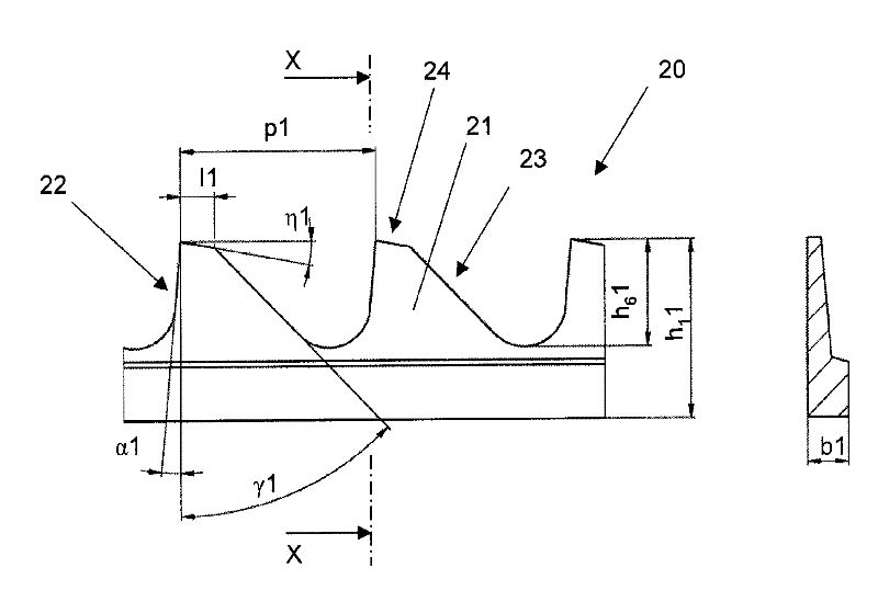
[0045] figure 1 A schematic diagram showing an embodiment of a first clothing wire 20 and a cross-sectional view at position X-X. Here a sawtooth wire is shown with teeth 21 having an overall height h of 4.5 mm 1 1 and 2.5mm tooth depth h 6 1. The teeth 21 of the clothing wire 20 are formed so as to create a face 24 . The face 24 is arranged to be inclined towards the rear side 23 of the tooth 21 so as to create a positive vertex angle η1. The front side 22 of the tooth 21 is inclined away from the rear side 23 of the tooth 21 so that a negative working angle α1 is formed. The teeth 21 of the first clothing wire 20 have a negative working angle α1 of 5° and a relief angle γ1 of 40°. The rib width b1 of the first clothing wire 20 was 1.0 mm. The tooth pitch p1 is 4.2 mm. The tooth 21 comprises a face 24 having a length l1 of 1.3 mm. The face 24 is slightly sloped with a positive posterior angle η1 of +5°. The first wire 20 is characterized by a negative working angle α...


PUM

PropertyMeasurementUnit
Tooth pitchaaaaaaaaaa

Abstract

The invention relates to all steel clothing of a roller for processing fibers in an opener, a scutcher, a cotton opener, or a carding machine. The all steel clothing comprises a first cloting wire and a second clothing wire. The first cloting wire comprises face portion teeth provided with a negative operating angle and a back top angle that ranges from -15 degrees to +15 degrees. The second clothing wire comprises teeth with a positive operating angle.

Description

technical field [0001] The invention relates to a metallic card clothing for an opener, a cleaning machine, a carding machine or a roller of a carding machine. Background technique [0002] Metallic card clothings are used in different fields of textile fiber processing. The invention relates to the combination of two card clothing wires used on weaving rollers in the fiber preparation process. Clothing wires in the form of sawtooth metal clothings are wound onto rollers helically and in close contact with each other. The general shape of serrated wires is described in the international standard ISO 5234. Metal card clothings pass their working angle α according to this standard, their relief angle γ, their relief angle η in the presence of a face l, their tooth pitch p and tooth depth h 6 , the total height h of steel wire 1 , and rib width b 1 characterization. The working angle α is the angle between the front side of the tooth and the perpendicular to the base, whe...

Claims


Application Information

Patent Timeline
IPC IPC(8): D01G15/88
CPCD01G15/88
Inventor J.伊滕F.哈斯勒N.帕夫劳P.阿尔茨
Owner GROB & CO AG
Why Eureka
Try Eureka