Fixed-point fatigue identification method for diagnosing faults of bearing and gear of transmission system

A fixed-point fatigue identification, bearing gear technology, applied in the direction of machine gear/transmission mechanism testing, etc., can solve the problems of failures that cannot be covered, damage, limited, etc.

Active Publication Date: 2012-09-05
北京唐智科技发展有限公司
View PDF3 Cites 9 Cited by
  • Summary
  • Abstract
  • Description
  • Claims
  • Application Information

AI Technical Summary

Problems solved by technology

[0048] In order to facilitate understanding and explanation, we define the cause of failure caused by not following the above design method as single fixed point fatigue. Bearing and gear faults caused by a class of single-point fatigue and the structural relationship that should be followed by the improved prevention design methods for this type of single-point fatigue faults have played a very good guiding role, guiding detection and forecasting in practical applications. Faults in this area, but human beings have limited understanding and control of nature. The original invention patent "a bearing and gear matching design method to reduce the failure rate of gear transmission system" cannot cover all the faults in the operation of bearings and gears. In other words, the single-fixed-point fatigue identification method proposed in the original invention patent still cannot distinguish other types of fatigue faults that still exist in the operation of bearings and gears. The single-point fatigue identification method still has the following one-sidedness: Fixed-point fatigue failure is the effect of one gear (such as a large gear) on another gear (such as a small gear), and emphasizes that the number of teeth Y passing through the meshing point of the load-bearing area between each hedging impact is an integer, ignoring the two existing in actual operation. The interaction of two gears, that is, when the number of teeth Y of one gear passing the meshing point is an integer plus 0.5, the tooth groove of the gear is located at the meshing point, while the other gear just passes the meshing point with the tooth top, and the abnormality of the two gears at this time The force destroys the tooth groove of one gear and the tooth top of another gear; the number of single-point fatigue failures J=C / Y of the gear identified by it must be an integer, that is, the single-point fatigue of these J teeth occurs every cycle of operation

Method used


Image

  • Fixed-point fatigue identification method for diagnosing faults of bearing and gear of transmission system
  • Fixed-point fatigue identification method for diagnosing faults of bearing and gear of transmission system
  • Fixed-point fatigue identification method for diagnosing faults of bearing and gear of transmission system

Examples


Embodiment 1

[0077] Example 1. Theoretical calculation and verification of "mutually fixed point fatigue" for a certain type of locomotive gear:

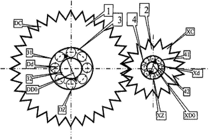
[0078] A fixed-point fatigue identification method for diagnosing transmission system bearing gear faults. If the bearing raceway (inner raceway is N or outer raceway is W) bearing area rolls over an integer X (the number of passes through the inner raceway is XN or through the outer raceway) When the number is XW) rollers, the gear meshing times Y is close to an integer +0.5 with a deviation not greater than S, and the ratio of the gear teeth C (the small gear is CX or the large gear is CD) to the meshing times Y is J=C / Y (the small gear is JX or the large gear is JD) is close to an integer with a deviation not greater than S, that is, ABS[J-CINT(J)]≤S, then it is identified as the gear fixed point fatigue of the gear matching the corresponding bearing The order is J (the small gear is JX or the big gear is JD), and both the damage spectrum and t...

Embodiment 2

[0098] Example 2, one of the theoretical calculation and verification of "quasi-fixed-point fatigue" for a certain type of locomotive gear:

[0099] A fixed-point fatigue identification method for diagnosing transmission system bearing gear faults. If the bearing raceway (inner raceway is N or outer raceway is W) bearing area rolls over an integer X (the number of passes through the inner raceway is XN or through the outer raceway) When the number is XW) rollers, the gear meshing times Y is close to an integer with a deviation not greater than S, and the gear tooth number C (small gear is CX, large gear is CD) and the ratio of the meshing times Y J=C / Y (The small gear is JX, the big gear is JD), the deviation from a similar integer is not more than 0.5, and when the gear rotates for an integer K cycles, FC=J*K is close to an integer with a deviation not greater than S, that is, ABS[FC- CINT(FC)]≤S, and INT(FC)≤C, it is recognized that the quasi-fixed-point fatigue of the gear mat...

Embodiment 3

[0118] Example 3, the second part of theoretical calculation and verification of "quasi-fixed-point fatigue" for a certain type of locomotive gear:

[0119] A fixed-point fatigue identification method for diagnosing transmission system bearing gear faults. If the bearing raceway (inner raceway is N or outer raceway is W) bearing area rolls over an integer X (the number of passes through the inner raceway is XN or through the outer raceway) When the number is XW) rollers, the gear meshing times Y is close to an integer with a deviation not greater than S, and the ratio of the number of teeth C of the gear (the small gear is CX or the large gear is CD) to the meshing times Y is J=C / Y( The small gear is JX or the large gear is JD) and the deviation of a similar integer is not more than 0.5, and when the gear rotates for an integer K cycles, FC=J*K is close to the integer with a deviation not greater than S, that is, ABS[FC-CINT( FC)]≤S, and INT(FC)≤C, it is recognized that the quasi...


PUM


Abstract

The invention discloses a fixed-point fatigue identification method for diagnosing faults of a bearing and a gear of a transmission system, comprising a pair of main gears (1) having a tooth number DC, an engagement pair of small gears (2) having a tooth number XC, a bearing (3) for supporting the main gears, and a bearing (4) for supporting the small gears. Parameters of the bearing (3) supporting the main gears are set as follows: intermediate diameter DDO, roller diameter Dd and roller number DZ; and the parameters of the bearing (4) supporting the small gears are set as follows: intermediate diameter XDO, roller diameter Xd and roller number XZ. The invention provides the method for identifying the faults caused by mutual fixed-point fatigue and quasi-fixed-point fatigue; and the method is characterized in that the parameters of the bearings are selected reasonably, and the mutual fixed-point fatigue and the quasi-fixed-point fatigue of the bearings and the corresponding matched gears are avoided, so that the fault rates of the bearings and the gears can reduced further.

Description

Technical field [0001] The invention relates to a fault mechanism diagnosis technology, in particular to a fixed-point fatigue identification method for diagnosing a transmission system bearing gear fault. Background technique [0002] The inventor disclosed a bearing and gear matching design method to reduce the failure rate of the gear transmission system in the Chinese patent "A bearing and gear matching design method to reduce the failure rate of the gear transmission system, which includes a pair of large teeth with DC Gear, the meshing pair of the pinion with the number of teeth XC, and the bearing supporting the large gear, the bearing supporting the pinion; set the bearing parameters supporting the large gear as: pitch diameter DD0, roller diameter Dd, roller number DZ; support The bearing parameters of the pinion are: pitch diameter XD0, roller diameter Xd, roller number XZ, as attached figure 1 . When discussing only a single gear and a single bearing, the simplified c...

Claims


Application Information

Patent Timeline
Patent Type & Authority Applications(China)
IPC IPC(8): G01M13/02
Inventor 唐德尧王智刘旷
Owner 北京唐智科技发展有限公司
Why Eureka
Try Eureka