

Camera module black spot detection system based on turntable
A camera module and detection system technology, applied in image communication, image enhancement, image analysis, etc., can solve problems such as misjudgment or missed judgment, facilitate observation, improve efficiency and accuracy, and reduce accidental errors Effect
- Summary
- Abstract
- Description
- Claims
- Application Information
AI Technical Summary
Problems solved by technology
Method used
Image

Examples
Embodiment 1
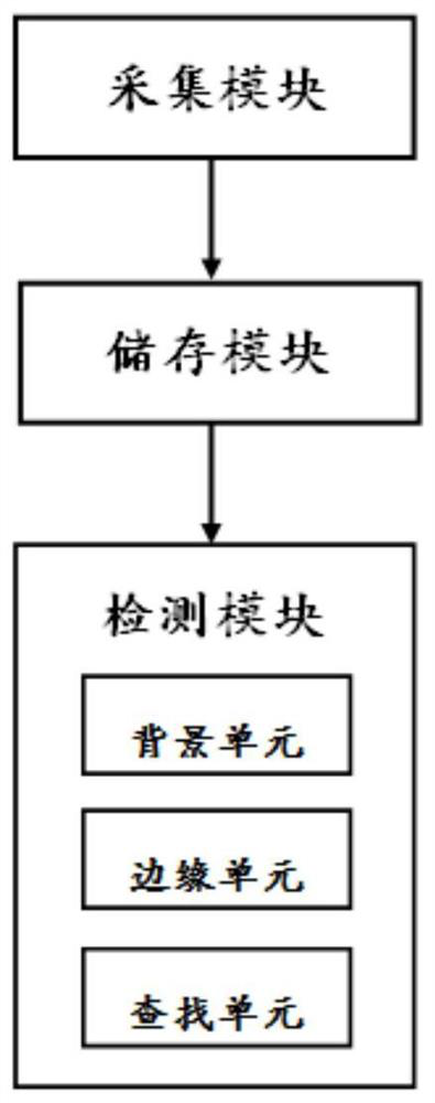
[0038] The embodiment of the camera module black spot detection system based on the turntable of the present invention is basically as attached figure 1 As shown, it includes: a camera module, used to take images; an acquisition module, used to collect images taken by the camera module; a storage module, used to store images taken by the camera module; a detection module, used to detect black spots on the images detection.
[0039] In this embodiment, in order to obtain a pure detection image of light scattering as much as possible, a white cover is placed on the front of the camera of the camera module. The area of the white cover is equal to the area of the camera, and the white cover can cover the entire camera field of view. The camera then captures an image of the white occlusion. After the shooting is completed, the acquisition module collects the image of the white occluder captured by the camera, and uses Gaussian filtering to reduce the noise of the image, thereb...
Embodiment 2
[0043] Compared with Example 1, the only difference is that
[0044] Before subtracting the model image obtained by background modeling from the original image, the edge unit distinguishes the normal part and the dark part of the model image, and extracts the position information of the lens imaging boundary. In this embodiment, the contour tracking method is adopted, and the method traces out the boundary by sequentially searching for edge points, and its basic operation process is as follows: first, search all the pixel points of the image in the order from left to right and from top to bottom in the image , first find the boundary point on the upper left of the image, and at least one of its four adjacent points of bottom, bottom left, right, and bottom right is a boundary point, which is recorded as B; then start from B, press right, bottom right, bottom , lower left, left, upper left, upper, upper right in order to find the boundary point C among adjacent points. If C is...
Embodiment 3
[0048] The only difference from Embodiment 2 is that in this embodiment, the subject and the cleaning structure are also included, and the reference point F is artificially marked on the subject, and an LED light is fixed at the reference point F, and the airflow blown out by the cleaning mechanism Clean up the subject to remove dust, hair, etc. from the surface.
[0049] When the camera shoots the object, the photo is displayed on the display screen, and the position of the reference point F is F1. Next, move the position of the reference point F on the subject to point G, and at this time, the position of the reference point G is G1 on the display screen. Move the position of the reference point F on the subject so that the point of the reference point F on the display screen is just on the edge of the display screen. Then take F1 as the origin to establish a Cartesian coordinate system on the display screen, so as to determine the coordinates of each pixel of the photograp...
PUM
 Abstract
Description
Claims
Application Information