

Liquid coating comb
A technique for coating liquid and comb, which is applied in the direction of hair comb, clothing, hairdressing equipment, etc., can solve the problems of poor scalp coating effect and easy flow, etc.
- Summary
- Abstract
- Description
- Claims
- Application Information
AI Technical Summary
Problems solved by technology
Method used
Image

Examples
Embodiment 1
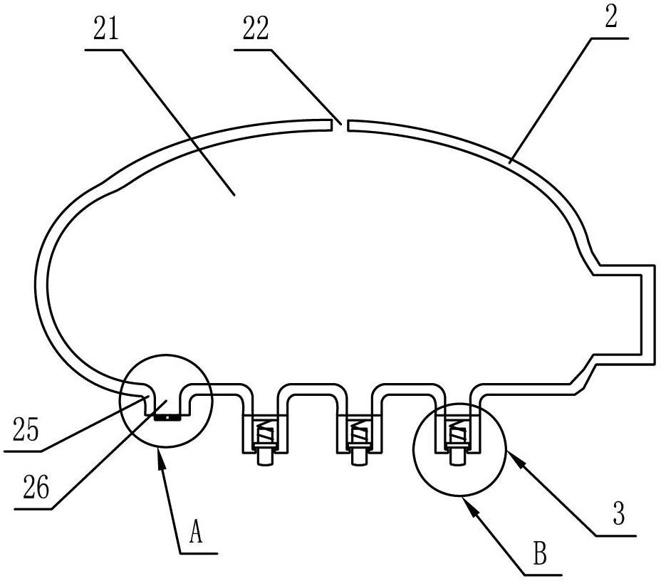
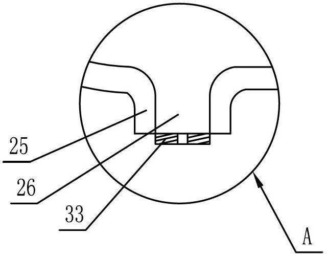
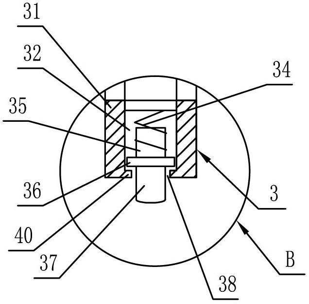
[0040] Such as figure 1 , figure 2 with image 3 As shown, the liquid-coating comb includes a comb body 2 and a comb tooth 25 connected with the comb body 2. The comb body 2 is provided with a comb body cavity 21 inside, and the comb tooth 25 is provided with a comb tooth cavity 26 communicated with the comb body cavity 21. The body cavity 21 is provided with a liquid inlet 22 , the comb cavity 26 is provided with a liquid outlet, and the comb 25 is threadedly connected with the liquid application device 3 . The liquid applicator 3 includes: a cylindrical liquid applicator body 31 with a liquid applicator chamber 32 communicated with the liquid outlet inside; a liquid applicator head located inside the liquid applicator chamber 32, and a rib 36 is arranged on the liquid applicator head; The liquid coating port 38 of the liquid coating chamber 32 is provided with a boss 40 compatible with the rib 36, so that the rib lower end 37 of the liquid coating head freely extends out ...
Embodiment 2
[0042] Such as Figure 4 , Figure 7 with Figure 8 As shown, the liquid coating comb includes a comb body 2, a comb handle 1 screwed to the right end of the comb body 2 and comb teeth 25 connected to the bottom of the comb body 2. The comb body 2 is provided with a comb cavity 21 inside, and the comb tooth 25 is provided with a comb cavity 26 communicating with the comb cavity 21 . The comb cavity 21 is provided with a liquid inlet, and the liquid inlet is provided with a rubber plug 23 . The comb tooth cavity 26 is provided with a liquid outlet, and the comb tooth 25 is bonded with the liquid application device 3 . The liquid applicator 3 includes: a cylindrical liquid applicator body 31 with a liquid applicator chamber 32 communicated with the liquid outlet inside; a liquid applicator head located inside the liquid applicator chamber 32, and a rib 36 is arranged on the liquid applicator head; The liquid coating port 38 of the liquid coating chamber 32 is provided with a ...
Embodiment 3
[0044] Such as Figure 5 , Figure 7 with Figure 8As shown, the liquid coating comb includes a comb body 2, a comb handle 1 integrally formed with the comb body 2, and comb teeth 25 connected to the bottom of the comb body 2. The comb body 2 is provided with a comb cavity 21 inside, and the comb tooth 25 is provided with a comb cavity 26 communicating with the comb cavity 21. The comb cavity 21 is provided with a liquid inlet, and the liquid inlet is provided with a plastic plug 24. The comb tooth cavity 26 is provided with a liquid outlet, and the comb tooth 25 is welded with the liquid application device 3 . The liquid application device 3 includes: a cylindrical liquid application device body 31 with a liquid application chamber 32 communicated with the liquid outlet inside; a liquid application head arranged inside the liquid application chamber 32, and a convex rib 36 is arranged on the liquid application head; The liquid coating port 38 of the liquid coating chamber ...
PUM
 Abstract
Description
Claims
Application Information