
Locking pull rod structure of cylindrical die strengthening device

A technology of reinforcement device and pull rod, which is applied in building construction, formwork/formwork/work frame, and on-site preparation of building components, etc., can solve the problems of large loss, waste, and complicated operation of sawing wood.

Inactive Publication Date: 2015-02-11
曹健厂
View PDF4 Cites 0 Cited by
  • Summary
  • Abstract
  • Description
  • Claims
  • Application Information

AI Technical Summary

Problems solved by technology

[0005] With this method of reinforcement, more square wood, steel nails, steel pipes, and iron wires are used. Saw steel pipes and sawn square wood are more wasted and wasteful. Too much steel nails will directly nail the column formwork and shorten the column formwork. The number of turnovers; this reinforcement method is relatively complicated to operate, and the reinforcement, disassembly, and installation quality inspection of the cylindrical formwork are all labor-intensive, resulting in high costs and slow progress
Due to the sunlight and rain in the process of using the square wood, it is easy to deform and deteriorate, and the operation of the reinforcement method is complicated, and the workers are prone to mistakes and omissions in the operation. Defective phenomena affecting quality such as pockmarked surface and honeycomb

Method used


Image

  • Locking pull rod structure of cylindrical die strengthening device
  • Locking pull rod structure of cylindrical die strengthening device
  • Locking pull rod structure of cylindrical die strengthening device

Examples


Embodiment Construction

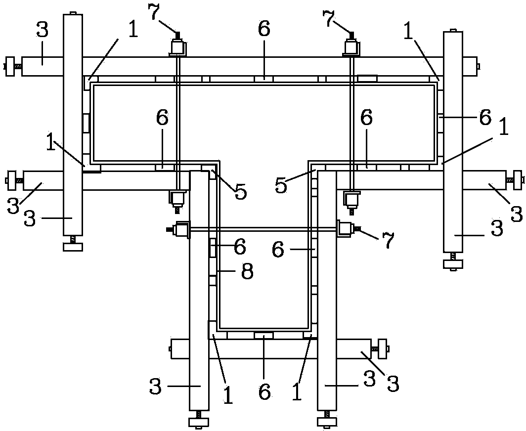
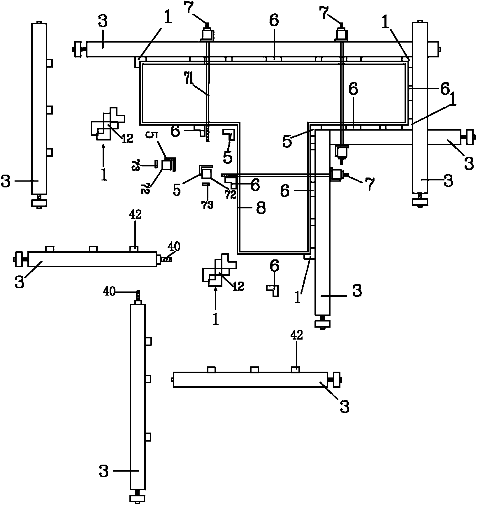
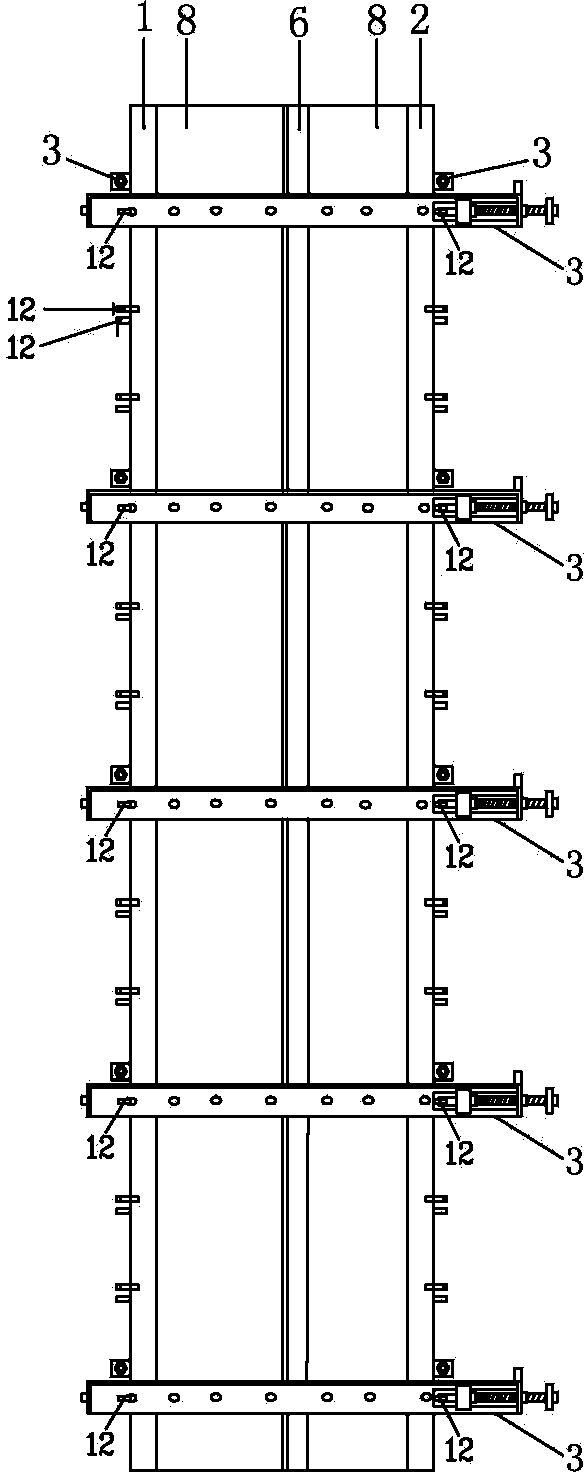
[0027] Such as Figure 1 to Figure 11 As shown, the present invention provides a kind of pull rod structure of the cylindrical mold reinforcement device, which mainly includes several male corner corner protectors 1, which respectively longitudinally wrap the male corners of the cylindrical mold 8 (not shown in the figure); A plurality of inner corner corner protectors 5, which longitudinally enclose the inner corners of the cylindrical mold 8 (not shown in the figure); Between the tie rods 3, the plurality of pull rods 3 are staggered two by two to surround the male corner corner protector 1, the female corner protector 5, the pressure plate encryption part 6, the combination groove buckle screw rod 7, Form enveloping reinforcement to column mold 8. A plurality of groove buckles 72 and screw rods 71, each of the screw rods 71 ​​passes through two adjacent karaoke rods 3 respectively.

[0028] Wherein, the male corner corner protector 1, the pull rod 3, the groove buckle scr...


PUM


Abstract

The invention provides a locking pull rod structure of a cylindrical die strengthening device, mainly comprising a plurality of external corner protection elements, a plurality of internal corner protection elements, a plurality of pressing plate compacting elements, a plurality of groove fasteners, screw rods, and a plurality of locking pull rods, wherein every two locking pull rods are staggered with each other and the locking pull rods respectively surround the external corner protection elements, the internal corner protection elements and the pressing plate compacting elements outside; a locking hole is formed on one side surface of a body of each locking pull rod; the locking hole is connected with a locking hook to adjust the use length of the locking pull rod; a thickening element is arranged outside one side of (closes the locking hole) the body of the rod; a locking tongue groove is formed at the rear end of the same side of the locking hole; a locking tongue connected with the locking hook which is used for connecting and fastening the external corner protection element is arranged in the locking tongue groove; the pressing plate compacting elements are longitudinally fixed among a cylindrical die and the locking pull rods; the screw rods respectively penetrate through every two adjacent locking pull rods; and the groove fasteners, the screw rods and the locking pull rods are crossed and jointed with each other to strength the cylindrical die in a surrounding manner. The locking pull rod structure of the cylindrical die strengthening device is simple and convenient for operation, and also capable of improving the speed of mounting and demounting the cylindrical die; and as a result, the recycling is realized.

Description

Technical field [0001] The present invention involves a column -shaped modified device, especially involving a stroke rod structure that prevent irrigation filling in the column -shaped modeling and explosive mold fastening device. Background technique [0002] At present, the pillar -shaped molding of the construction industry is reinforced. Generally, it is reinforced by plywood, humane, steel nails, steel pipes, iron wires, screws, column cards and other materials. [0003] The general reinforcement method is to connect the template to the column -shaped mold during installation. Put the tightly nail in the column -shaped mold corner and combine the iron wire reinforcement corner to prevent leakage and swelling the mold.Fix the beyl wood on the columnar template, then encrypt the pressure plate, and then use the iron tube to bind the steel pipe of the saw section, combine the screw reinforcement or use the beyl wood and add the pressure plate, and then nail the beef fixing sec...

Claims


Application Information

Patent Timeline
Patent Type & Authority Patents(China)
IPC IPC(8): E04G13/02
Inventor 曹健厂
Owner 曹健厂
Learn More