Acquisition method of sliding pressure curve of steam turbine by using main steam flow as scheduling variable

A technology of main steam flow and sliding pressure curve, which is applied in the directions of mechanical equipment, engine components, machines/engines, etc., to achieve the effect that the determination method is simple and easy to implement and easy to implement.

Active Publication Date: 2012-09-12
NANJING POWER HORIZON INFORMATION TECH CO LTD
View PDF5 Cites 26 Cited by
  • Summary
  • Abstract
  • Description
  • Claims
  • Application Information

AI Technical Summary

Problems solved by technology

[0006] The purpose of the present invention is to provide a method for obtaining the sliding pressure curve of a steam turbine with the main steam flow as a scheduling variable for the problem that one sliding pressure curve can not be used to meet the operating conditions of the variation of extraction steam and the change of back pressure in the past.

Method used


Image

  • Acquisition method of sliding pressure curve of steam turbine by using main steam flow as scheduling variable
  • Acquisition method of sliding pressure curve of steam turbine by using main steam flow as scheduling variable
  • Acquisition method of sliding pressure curve of steam turbine by using main steam flow as scheduling variable

Examples


specific Embodiment approach 1

[0020] Specific implementation mode one: the following combination Figure 1 to Figure 3 To describe this embodiment,

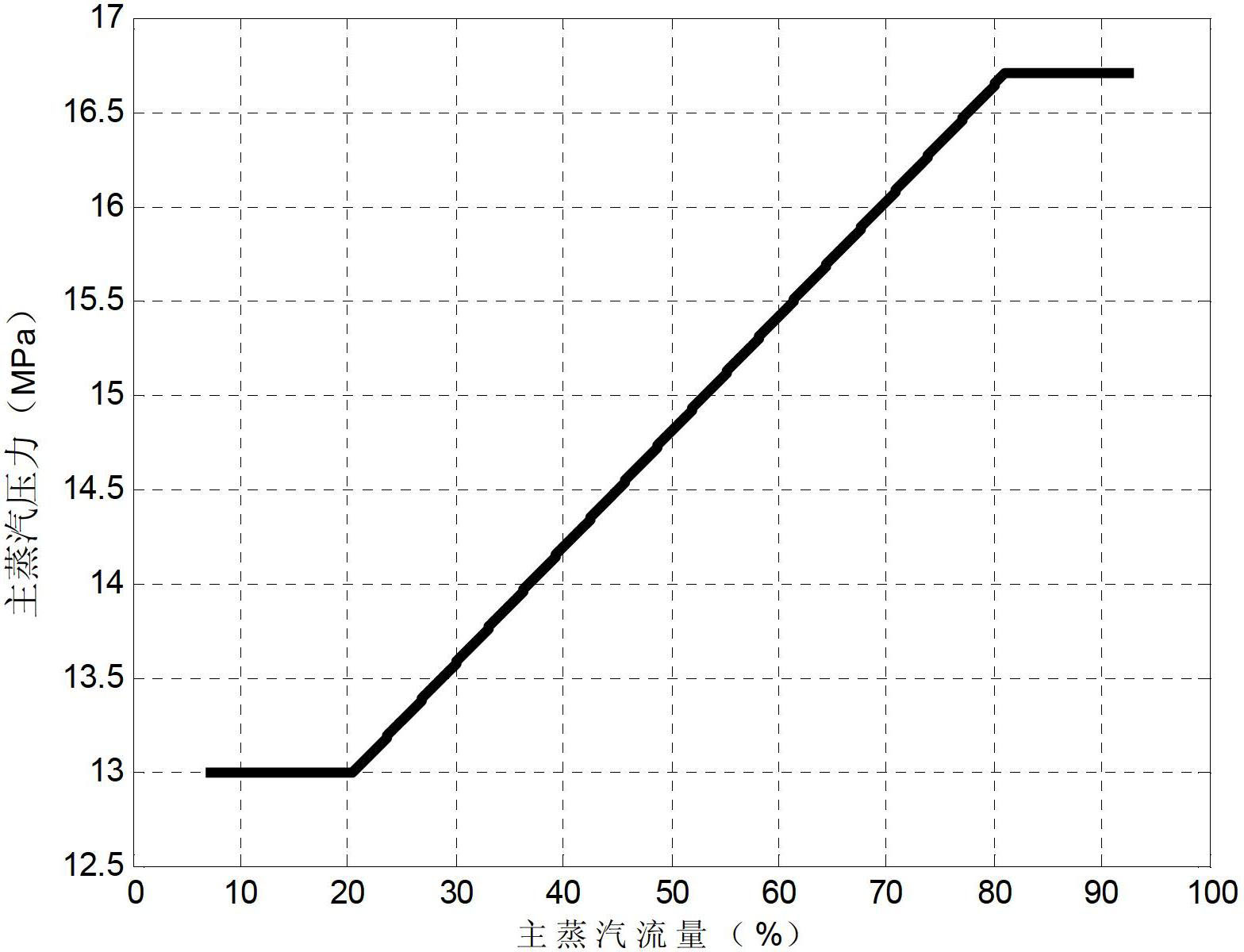
[0021] A method for obtaining the sliding pressure curve of a steam turbine using the main steam flow as a scheduling variable, the implementation steps of the method are as follows:

[0022] Step 1: According to the type of heating and extraction steam unit, select M main steam flows according to the order of main steam flow values ​​from small to large; M is an integer greater than 2; perform the following step 2 for each main steam flow to four, then go to step five

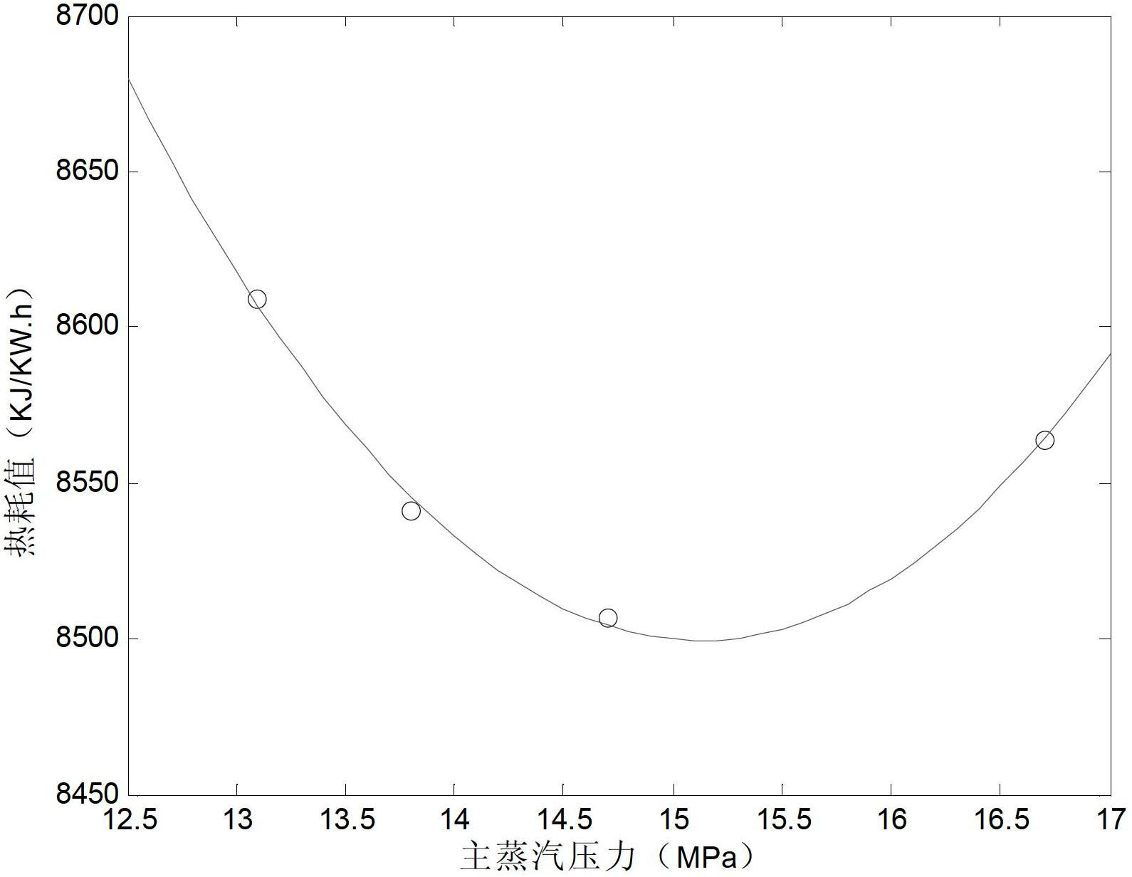
[0023] Step 2: Under the selected main steam flow rate, keep the heating and extraction steam volume and the vacuum of the condenser unchanged under the main steam flow rate. The main steam flow rate is selected from N different main steam pressure values ​​of the heating and extraction unit, and N is an integer greater than 4;

[0024] Step 3: At each main steam pressure, keep the main st...

specific Embodiment approach 2

[0033] Specific implementation mode two: the following combination Figure 1 to Figure 3 Describe this embodiment. This embodiment is to further explain the calculation of the unit test heat rate corresponding to each main steam pressure set value described in step 3 of the first embodiment. The method for determining the sliding pressure curve of the steam turbine, the method for calculating the unit test heat rate corresponding to each main steam pressure setting value described in step 3 is:

[0034] According to the calculation formula of heat consumption value:

[0035] H rt = F ms × H ms - F fw × H fw - F shsp ...

specific Embodiment approach 3

[0037] Embodiment 3: This embodiment is a specific process of obtaining the sliding pressure operation curve of the heat supply and steam extraction unit from the method described in the present invention.

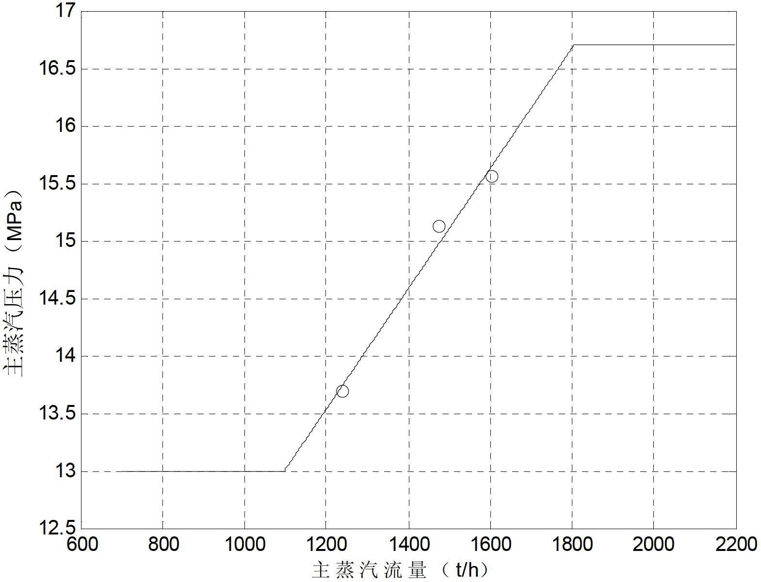
[0038] In this embodiment, the heat supply and steam extraction unit is a thermal power steam turbine unit of a 600MW unit, and the process of applying the method of the present invention to obtain the steam turbine sliding pressure curve is as follows:

[0039] Step 1: Select the main steam flow rate as 1230t / h, 1450t / h, 1600t / h, 1700t / h respectively, and keep the heat supply and extraction steam volume and condenser vacuum constant under one main steam flow rate; for each main steam flow rate For steam flow, perform the following steps 2 to 4 respectively, and then perform step 5

[0040] Step 2: Change the main steam pressure of the unit under the main steam flow rate of 1230t / h. The specific values ​​of the main steam pressure points are as follows:

[0041]

[004...


PUM


Abstract

The invention provides an acquisition method of a sliding pressure curve of a steam turbine by using a main steam flow as a scheduling variable, relates to a determining method of a sliding pressure curve, and aims at solving the problem that the heat supply steam extraction capacity variation and back pressure variation operation status cannot be fulfilled by one sliding pressure curve. The method comprises the following steps: selecting M main steam flows according to the type of a heat supply steam extraction unit, wherein M is an integer of greater than 2, and each main steam flow is respectively subjected to the following steps: N different main steam pressure values of the heat supply steam extraction machine are selected with the main steam flow being the selected main steam flow, and N is an integer of greater than 4; calculating heat consumption values of the heat supply steam extraction unit; performing curve fitting on the N main steam pressure values and corresponding heat consumption values thereof according to a least square method to determine an optimal main steam pressure value; and performing linear fitting on the acquired M main steam flows and the corresponding optimal main steam pressure data thereof to acquire a final sliding pressure operation curve. The acquisition method is used for determining the sliding pressure curve of the steam turbine.

Description

technical field [0001] The invention relates to a method for obtaining a sliding pressure curve. Background technique [0002] With the development of the national economy, the number of large-capacity units is increasing, the capacity of the power grid is increasing, and the peak-to-valley difference of the power grid is also increasing. The load of the power grid can only be operated at full load in summer. Therefore, the main unit of the power grid has to participate in load reduction and peak shaving operation frequently, and must often operate with a large range of variable operating conditions between 55% and 90% load. Under variable operating conditions, the steam turbine deviates from the design operating conditions, which reduces the economic benefits of the unit. At present, generator sets in power plants generally adopt constant-slip-constant compound sliding pressure operation mode: constant pressure operation mode is adopted in high load area; sliding pressure ...

Claims


Application Information

Patent Timeline
Patent Type & Authority Applications(China)
IPC IPC(8): F01D17/00
Inventor 刘金福万鹏程刘娇万杰于达仁
Owner NANJING POWER HORIZON INFORMATION TECH CO LTD
Why Eureka
Try Eureka