Rubber belt type energy accumulator

A technology of rubber belts and accumulators, which is applied in the direction of machines/engines, elastic motors, mechanical equipment, etc., can solve the problems of high technical difficulty and high cost, and achieve the effects of high energy density, light weight, and high energy conversion efficiency

Inactive Publication Date: 2012-09-12
SHANDONG UNIV OF TECH
View PDF4 Cites 30 Cited by
  • Summary
  • Abstract
  • Description
  • Claims
  • Application Information

AI Technical Summary

Problems solved by technology

Flywheel energy storage is still immature

Method used


Image

  • Rubber belt type energy accumulator
  • Rubber belt type energy accumulator
  • Rubber belt type energy accumulator

Examples


specific Embodiment approach

[0019] The present invention will be described in detail below in conjunction with the accompanying drawings and embodiments.

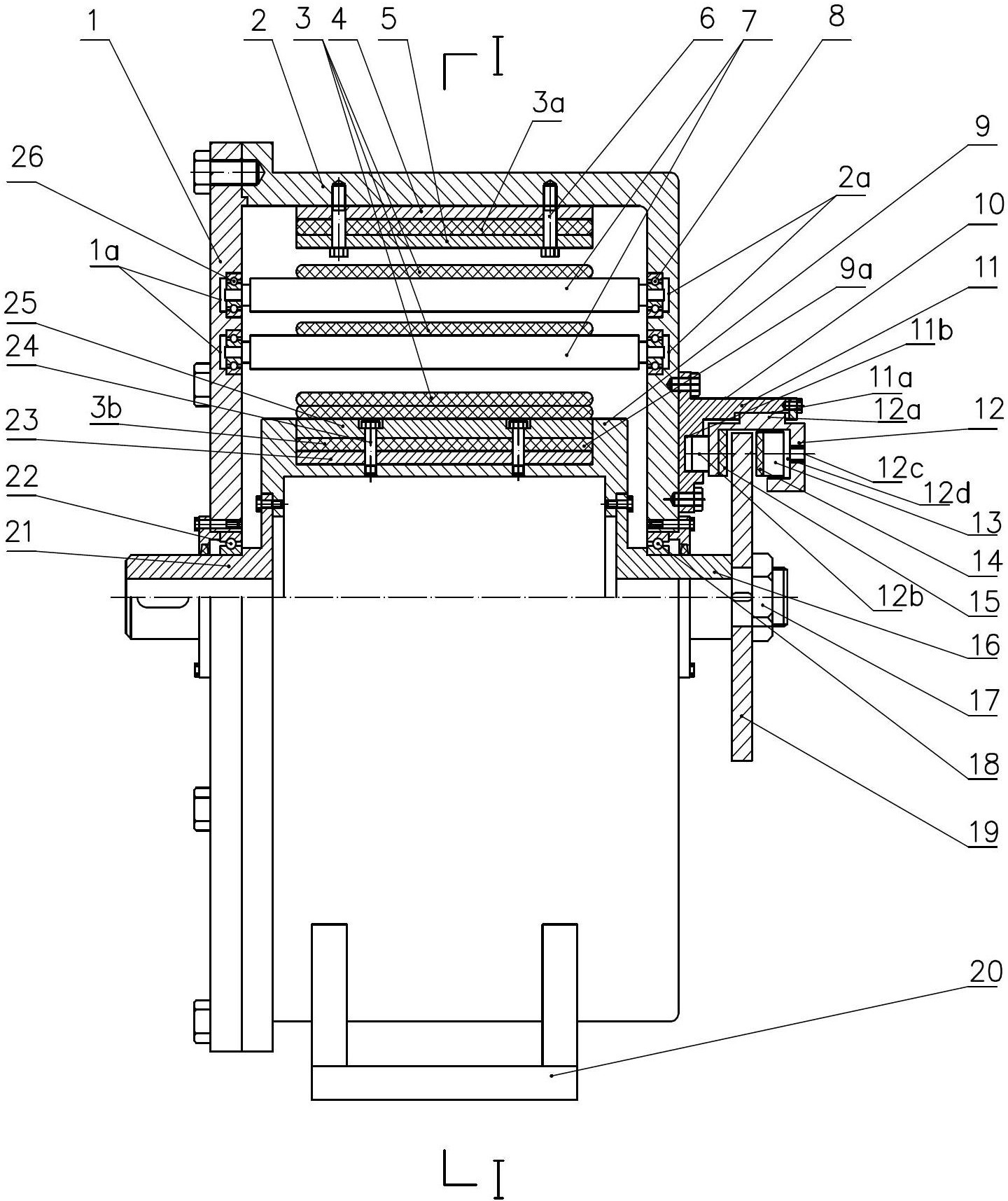
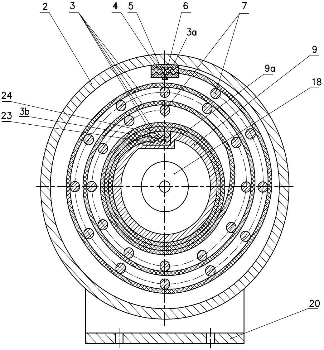
[0020] Such as figure 1 and figure 2 As shown, the rubber belt accumulator according to Embodiment 1 of the present invention includes: an end cover 1, a housing 2, a rubber belt 3, a roller 9, a plurality of guide rollers 7, a power transmission shaft 21, a brake shaft 16 and a brake shaft. Moving device 10, wherein rubber band 3 adopts single rubber band.

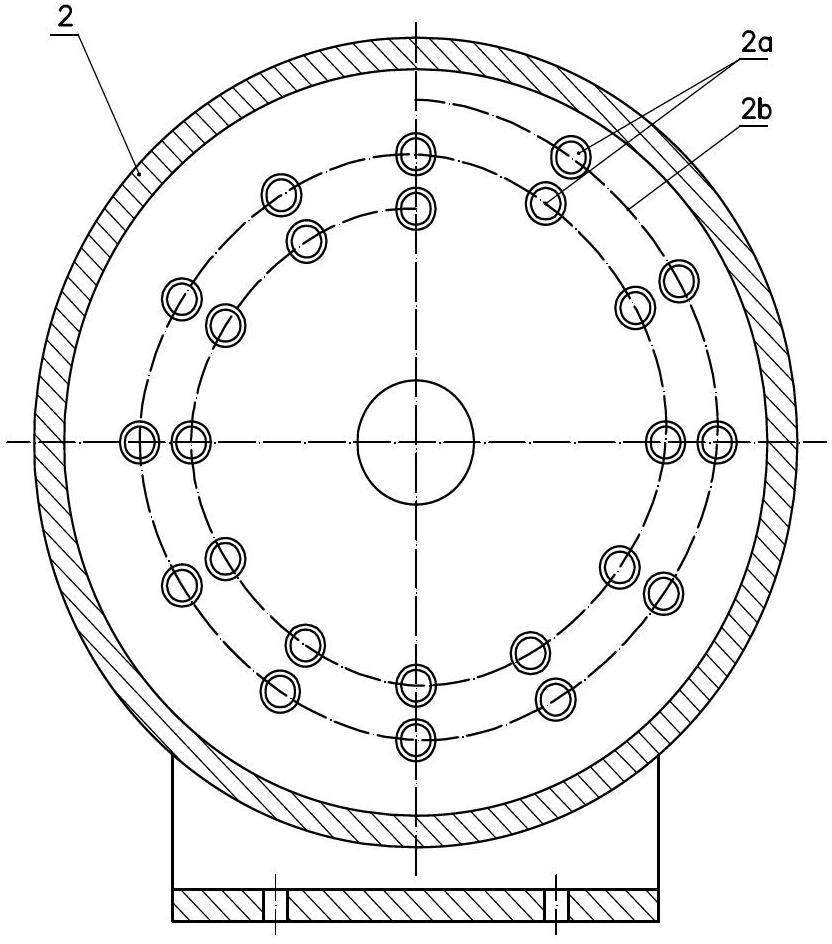
[0021] The end cover 1 and the shell 2 are split structures. The end cover 1 and the shell 2 are fixedly connected by bolts. The end cover and the shell form a cavity inside. In order to ensure the accuracy of the installation position of the end cover 1 and the housing 2, the right side of the housing 2 is fixedly connected to the brake device 10, and the housing 2 has a mounting base 20, which is used to fix the rubber belt type accumulator during use. The left end of the drum 9 is connecte...


PUM


Abstract

The invention discloses a rubber belt type energy accumulator and aims to provide a novel rubber belt type energy accumulator which is high in energy transformation ratio, high in energy density, light in weight and simple in structure. The rubber belt type energy accumulator comprises an end cover, a casing, a rubber belt, a rotary drum, multiple guiding rolling shafts, a power transmission shaft, a brake shaft and a brake device, wherein the rubber belt is supported by the multiple guiding rolling shafts to extend along an approximate Archimedes spiral. The rubber belt type energy accumulator can be used for storing and transforming kinetic energy; in the energy accumulation process, the kinetic energy inputted to the energy accumulator can be stored in the form of rubber belt elastic potential energy; and in the energy releasing process, the elastic potential energy stored in the rubber belt is transformed into kinetic energy which is outputted to the external environment. The rubber belt type energy accumulator is suitable for recycling braking energy of equipments such as vehicles and elevators.

Description

technical field [0001] The present invention relates to an accumulator, more particularly, the present invention relates to a rubber belt accumulator. Background technique [0002] During the movement of vehicles, elevators and other equipment, frequent braking and starting often occur. During the braking process, the kinetic energy of vehicles, elevators and other equipment is converted into heat energy through the braking device and is wasted. In order to make full use of the braking energy of vehicles, elevators and other equipment, there are usually three braking energy recovery methods: [0003] The first braking energy recovery method is to convert the kinetic energy of vehicles, elevators, etc. into hydraulic energy and air pressure energy through secondary components such as hydraulic pumps and air compressors, and store them in accumulators. Hydraulic or pneumatic accumulators are mainly divided into pneumatic, gravity and spring types. Inflatable accumulators in...

Claims


Application Information

Patent Timeline
IPC IPC(8): F03G1/00
Inventor 曲金玉周英超曲桂娴
Owner SHANDONG UNIV OF TECH
Why Eureka
Try Eureka