Backlight module

A backlight module and backlight technology, applied in optics, light guides, light sources, etc., can solve problems such as poor coupling efficiency, insufficient intensity, and bright line areas, and achieve increased stability, low cost, and thinning Effect

Active Publication Date: 2012-09-12
TCL CHINA STAR OPTOELECTRONICS TECH CO LTD
View PDF5 Cites 19 Cited by
  • Summary
  • Abstract
  • Description
  • Claims
  • Application Information

AI Technical Summary

Problems solved by technology

[0006] However, due to the limitation of the shape of the convex rib 502', there is a certain distance between the light coupling position of the backlight 400', and the thinned light guide plate 300' has a sagging phenomenon on the light incident side due to insufficient strength (such as image 3 As shown), the coupling error is caused, and a large amount of light emitted by the backlight is exposed, which not only deteriorates the coupling efficiency, but also tends to cause a bright line area near the light incident surface of the light guide plate 300'

Method used


Image

  • Backlight module
  • Backlight module
  • Backlight module

Examples


Embodiment Construction

[0028] In order to further illustrate the technical means adopted by the present invention and its effects, the following describes in detail in conjunction with preferred embodiments of the present invention and accompanying drawings.

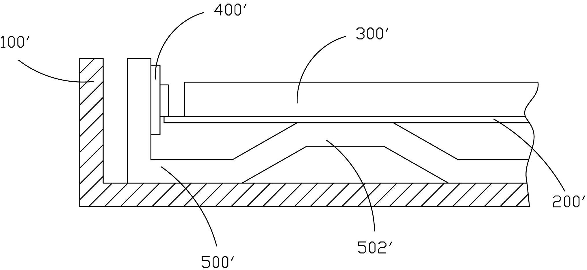
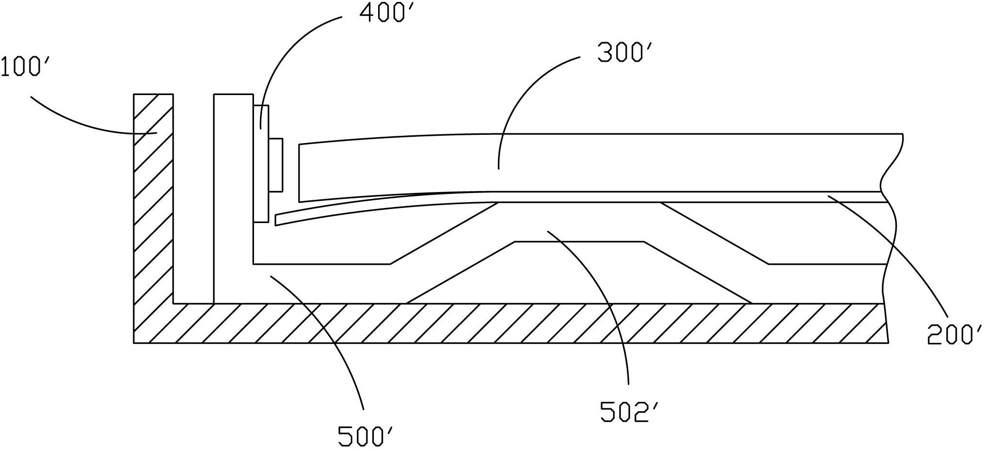
[0029] see Figure 4 and Figure 5 , the present invention provides a backlight module, comprising: a backplane 2, a light guide plate 4 arranged in the backplane 2, a backlight source 6 arranged in the backplane 2, and a backlight 6 arranged in the backplane 2 and supporting the light guide plate 4 and The support element 8 of the backlight 6 supports the light guide plate 4 and the backlight 6 at the same time, so that the light guide plate 4 and the backlight 6 form a stable alignment relationship, increasing the stability of optical coupling.

[0030] The supporting element 8 is arranged in a stepped shape, and includes a first supporting portion 82 supporting the backlight 6 and a second supporting portion 84 connected to the first suppo...


PUM


Abstract

The invention provides a backlight module which comprises a back plate, a light guide plate, a backlight source and a support element, wherein the light guide plate is arranged in the back plate; the backlight source is arranged in the back plate; and the support element is arranged in the back plate and supports the light guide plate and the backlight source. The backlight module provided by the invention uses the support element to support the backlight source and the light guide plate simultaneously, thus the backlight source and the light guide plate form the stable counter-point relationship, the stability of light coupling is increased, and the backlight module is simple in structure, is low in cost, and is beneficial to realization of thinning.

Description

technical field [0001] The invention relates to the field of liquid crystal display, in particular to a backlight module. Background technique [0002] A liquid crystal display (LCD, Liquid Crystal Display) has many advantages such as a thin body, power saving, and no radiation, and has been widely used. Most of the liquid crystal display devices currently on the market are backlight liquid crystal display devices, which include a liquid crystal panel and a backlight module. The working principle of the liquid crystal panel is to place liquid crystal molecules between two parallel glass substrates. There are many vertical and horizontal small wires between the two glass substrates. The direction of the liquid crystal molecules is controlled by electrifying or not, and the light of the backlight module is refracted. Come out to generate the picture. Since the liquid crystal panel itself does not emit light, the light source provided by the backlight module is needed to disp...

Claims


Application Information

Patent Timeline
IPC IPC(8): F21S8/00F21V17/00F21V19/00G02F1/13357F21Y101/02
CPCG02B6/0085G02B6/0091
Inventor 萧宇均张彦学
Owner TCL CHINA STAR OPTOELECTRONICS TECH CO LTD
Why Eureka
Try Eureka