In-tube evaporator

A technology of evaporator and evaporating tube, applied in the direction of evaporator/condenser, heat exchanger type, indirect heat exchanger, etc., can solve the problems of small proportion, limited heat exchange effect, unfavorable system operation control, etc. Simple processing, good heat exchange effect, and the effect of reducing flow resistance

Inactive Publication Date: 2012-09-12
DALIAN MARITIME UNIVERSITY
View PDF2 Cites 1 Cited by
  • Summary
  • Abstract
  • Description
  • Claims
  • Application Information

AI Technical Summary

Problems solved by technology

Flow patterns such as bubbles and plugs will increase flow resistance and operational instability, which will adversely affect the control of system operation
Annular and thin-film evaporation flow patterns have excellent heat transfer performance, but they account for a small proportion in the entire tube pass, which has a very limited effect on improving the heat transfer of the entire system

Method used


Image

  • In-tube evaporator
  • In-tube evaporator

Examples


Embodiment Construction

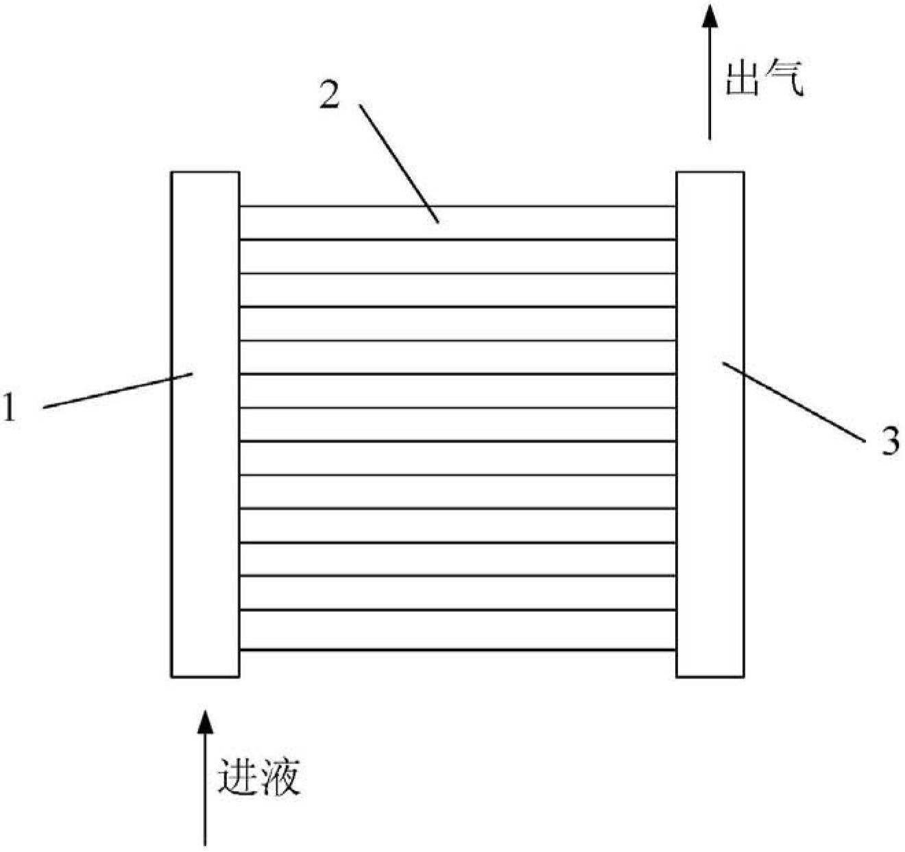
[0012] The present invention is described in further detail by the following examples. Such as figure 1 As shown, a tube evaporator includes a liquid distribution pipe 1, an evaporation pipe 2 and an air outlet pipe 3, one end of the evaporation pipe 2 is connected to the liquid distribution pipe 1, and the other end is connected to the air outlet pipe 3; the liquid distribution pipe 1 The inside is filled with a porous structure; one end of the evaporation tube 2 is in close contact with the porous structure of the liquid distribution tube 1; the diameter of the outlet tube 3 is larger than the diameter of the evaporation tube 2 or the sum of the diameters of multiple evaporation tubes 2, but not more than 3 times the sum of the diameters of the root evaporation tubes 2;

[0013] The porous structure is a metal particle sintered layer or a multi-layer wire mesh, the metal particle sintered layer adopts 30-70 μm metal particles, and the multi-layer wire mesh adopts a 200-400 ...


PUM


Abstract

The invention discloses an in-tube evaporator, which comprises a liquid distribution tube, evaporation tubes and an air outlet tube, wherein the liquid distribution tube is filled with a porous structural matter; one end of each evaporation tube is in close contact with the porous structural matter of the liquid distribution tube; the diameter of the air outlet tube is greater than the diameter of each evaporation tube or the sum of the diameters of a plurality of evaporation tubes, but does not exceed three times the sum of the diameters of the evaporation tubes; the porous structural matter is a metal particle sintered layer or a multi-layer metal mesh; the metal particle sintered layer is made of metal particles of 30-70 mum; the multi-layer metal mesh is a metal mesh of 200-400 meshes; and each evaporation tube is a metal sintered tube or a metal fluted tube. According to the in-tube evaporator, liquid is uniformly arranged in the evaporation tubes by using capillary force of a porous structure in the liquid distribution tube, and a thin film evaporation flow pattern is formed. Since only one thin film evaporation flow pattern exists in the evaporation tube, the in-tube evaporator has an excellent heat exchange effect, and the flow resistance and the instability in operation are greatly reduced.

Description

technical field [0001] The invention relates to thermal heat exchange equipment, in particular to an in-tube evaporator. Background technique [0002] In-tube evaporator is a kind of thermal heat exchange equipment, which is widely used in power, chemical industry, air conditioning and refrigeration and other fields. Regardless of the heating method, the inlet of the evaporator in the tube is pure liquid, and after the full length of the tube is vaporized, the outlet is basically pure gas. This single-tube evaporation and boiling process will inevitably lead to complex gas-liquid two-phase flow. During the gasification and heat exchange process in the tube, the gas-liquid will be in the flow patterns of bubble, plug, ring and thin film evaporation according to the dryness. Flow patterns such as bubbles and plugs will increase flow resistance and operational instability, which will adversely affect the control of system operation. Annular and thin-film evaporation flow pat...

Claims


Application Information

Patent Timeline
Patent Type & Authority Applications(China)
IPC IPC(8): F28D3/02F28D3/04F25B39/02
Inventor 董景明潘博潘新祥彭博
Owner DALIAN MARITIME UNIVERSITY
Why Eureka
Try Eureka