Load remote automatic control power supply device

A power supply device and remote start-up technology, applied in the direction of circuit devices, electrical components, etc., can solve problems such as power consumption, potential safety hazards, and lack of automatic cut-off function

Inactive Publication Date: 2012-09-12
郭胜利 +1
View PDF4 Cites 10 Cited by
  • Summary
  • Abstract
  • Description
  • Claims
  • Application Information

AI Technical Summary

Problems solved by technology

If the external line is disconnected due to some factors, the front end (switch knife) will not automatically cut off the power output, it must be cut off manually
Since it is impossible to know when the outside line is disconnected in time, and the cu

Method used


Image

  • Load remote automatic control power supply device
  • Load remote automatic control power supply device
  • Load remote automatic control power supply device

Examples


Embodiment 1

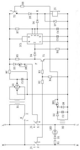
[0016] like figure 1 As shown: the single-phase electric load remote automatic control power supply device described in this embodiment is composed of a complete machine working power supply circuit, a remote start command recognition circuit, a power supply, power-off execution control circuit and an on-load continuous power supply recognition control circuit. The external line (DC impedance) in this embodiment refers to the loop line between the front end of the power control switch and the load terminal, and the power control switch refers to the switch blade.

[0017] The working power circuit of the complete machine is composed of a switch K, a transformer B, a bridge rectifier stack Q1, a filter capacitor C1, and a three-terminal voltage stabilizing circuit WY. The working process is: the AC power is sent to the primary of the transformer B1 through the switch K, and after being stepped down by the transformer, it is sent to the bridge pile Q1 for rectification, and t...

Embodiment 2

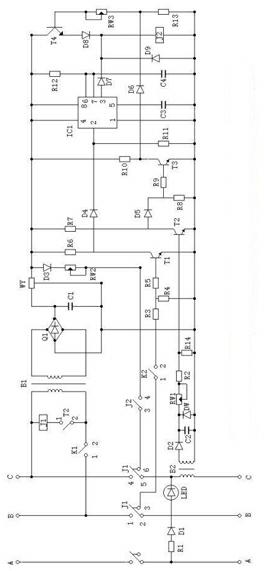
[0026] like figure 2 As shown: the configuration of the three-phase electric load remote automatic control power supply device described in this embodiment is basically the same as that of the single-phase electric load remote automatic control power supply device described in Embodiment 1. The identification circuit is composed of a power supply, power-off execution control circuit and an on-load continuous power supply identification control circuit. The external line also refers to the line between the front end of the power control switch and the load terminal, and the power control switch refers to the switch knife. The main difference is: in the working power circuit of the whole machine, the AC power is sent to the primary of the transformer B1 through the switch K, and after the voltage is stepped down by the transformer, it is sent to the bridge stack Q1 for rectification to obtain a pulsed DC voltage, which is passed through the filter capacitor C1 After filtering...


PUM


Abstract

The invention discloses a load remote automatic control power supply device, which consists of a whole machine work power supply circuit, a remote startup instruction and shutoff instruction identification circuit, a power-up and power-down execution control circuit and a load continuous power-up and no-load automatic power-down identification circuit. Instructions are started by adopting the loop line direct current impedance principle of outward lines of a power control terminal and a load terminal, so as to finish a power transmission process; and an alternating current electromagnetic induction principle is adopted to identify and control a working state of a load and control the output of a power supply, so as to finish power output or power shut-off. According to the load remote automatic control power supply device, the function of power supply control is completed, the startup and the shutoff of the power control terminal are remotely controlled from the load terminal, and then, the functions that the power is automatically supplied when the load consumes power, the power is automatically shut off when the load does not consume power, and the power is also automatically shut off when a line is in interruption are achieved, so that the aims of improving the safety of power transmission and saving electric energy are reached.

Description

technical field [0001] The invention belongs to the technical field of electronic power control, and mainly relates to a load remote automatic control power supply device. Supply and shutdown for all power controls. Background technique [0002] As we all know, the working power of all electrical equipment, machines and various household appliances comes from the electric power source, and controlling the power source controls the power source of the electrical equipment. The current formal tools for controlling power supply are various "switches", "switches", "circuit breakers", "contactors" and so on. Turning on or off these "tools" just reaches the supply or cut off of control power. In actual work and production, there is a certain distance between the power "switch", "switch" and "contactor" and the actual electrical equipment. The general procedure is to first turn on the "switch" and "switch" of the main power supply. It has been sent to the input end of the electr...

Claims


Application Information

Patent Timeline
IPC IPC(8): H02J13/00
Inventor 郭胜利吉圣杰
Owner 郭胜利
Why Eureka
Try Eureka