Passive clamping type piezoelectric actuator

A piezoelectric driver and clamping technology, applied in the direction of piezoelectric effect/electrostrictive or magnetostrictive motors, electrical components, generators/motors, etc., can solve the problem of poor control flexibility, clamp amplification structure form Complexity and other problems, to achieve the effect of reducing machining accuracy, simple structure and accurate positioning

Active Publication Date: 2012-09-12
HARBIN INST OF TECH
View PDF4 Cites 7 Cited by
  • Summary
  • Abstract
  • Description
  • Claims
  • Application Information

AI Technical Summary

Problems solved by technology

[0005] The purpose of the present invention is to solve the problem that the adjustment of the pretightening force of the existing passive clamp piezoelectric actuator is controlled by matching the interference, and its control flexibility is relatively poor. At the same time, the structural form of its clamp amplification structure is relatively complicated problem, and then provide a passive clamp piezoelectric driver

Method used


Image

  • Passive clamping type piezoelectric actuator
  • Passive clamping type piezoelectric actuator
  • Passive clamping type piezoelectric actuator

Examples


specific Embodiment approach 1

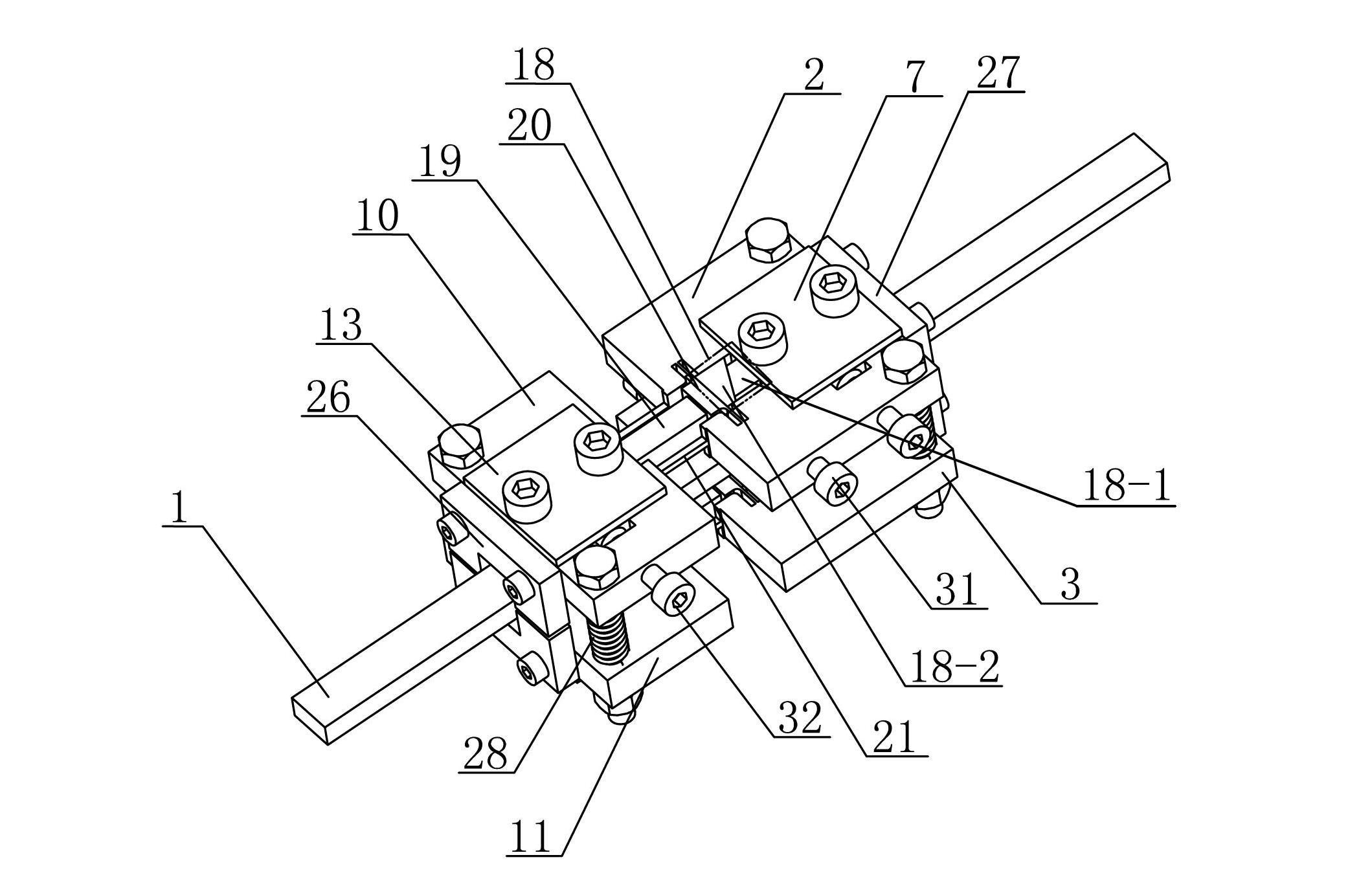
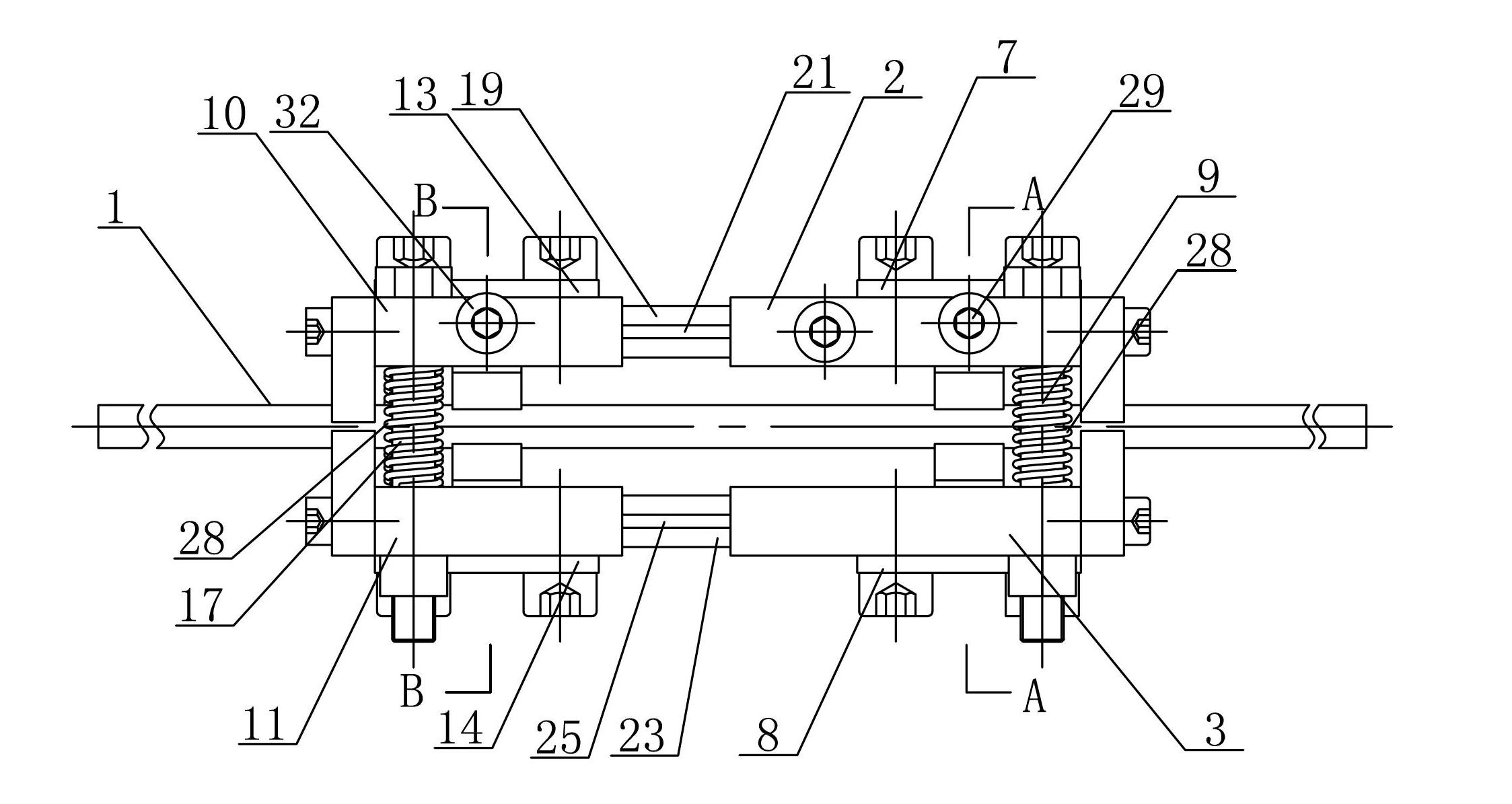
[0014] Specific implementation mode one: combine Figure 1-Figure 6 Describe this embodiment, the passive clamping type piezoelectric actuator of this embodiment includes a first clamping mechanism, a driving mechanism, a second clamping mechanism and a guide rail 1,

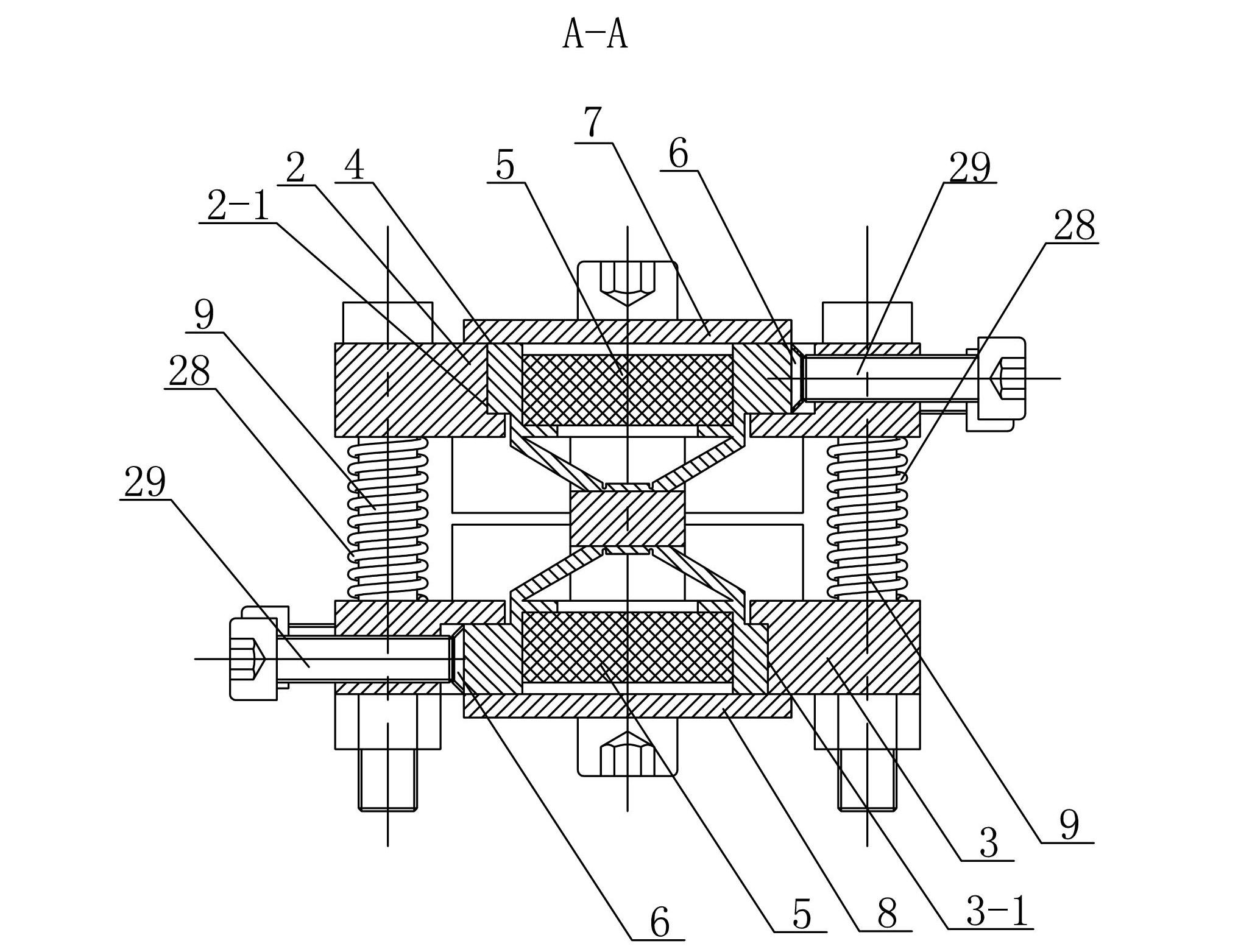
[0015] The first clamp mechanism includes a first upper base plate 2, a first lower base plate 3, a first clamp triangular amplification mechanism 4, a first upper cover plate 7, a first lower cover plate 8, two first clamp piezoelectric stacks Stack 5, two first disc springs 6 and two first cylinders 9, the first upper base plate 2 and the first lower base plate 3 are arranged in parallel up and down, and the first upper base plate 2 and the first lower base plate 3 pass through two The first cylinder 9 is supported and connected, and the centers of the first upper base plate 2 and the first lower base plate 3 are respectively provided with a first upper clamping piezoelectric stack placement hole 2-1 and a fir...

specific Embodiment approach 2

[0028] Specific implementation mode two: combination image 3 and Figure 5 Describe this embodiment, the stiffness of the first disc spring 6 of this embodiment is greater than the stiffness of the first clamping triangular amplifying mechanism 4 and smaller than the output stiffness of the first clamping piezoelectric stack 5, the stiffness of the second disc spring 16 is greater than The stiffness of the second clamping triangular amplification mechanism 12 is smaller than the output stiffness of the second clamping piezoelectric stack 15 . In this way, when the first clamping piezoelectric stack 5 is pre-tightened, the first disc spring 6 is connected in series with the rigidity of the first clamping triangular amplifying mechanism 4, and the deformation mainly occurs in the first clamping triangular amplifying mechanism 4; When the second clamping piezoelectric stack 15 is pre-tightened, the stiffness of the second disc spring 16 is connected in series with the second cl...

specific Embodiment approach 3

[0029] Specific implementation mode three: combination figure 1 To describe this embodiment, the tensile stiffness of the upper telescopic rod 21 of this embodiment is smaller than the output stiffness of the upper driving piezoelectric stack 19 , and the tensile stiffness of the lower telescopic rod 25 is smaller than the output stiffness of the lower driving piezoelectric stack 23 . In this way, the tensile stiffness of the telescopic rod should be smaller than the output stiffness of the driven piezoelectric stack as much as possible under the premise of satisfying the stiffness conditions, so as to give full play to the output capacity of the driven piezoelectric stack. In addition, it has a simple structure and is easy to process. , the amount of deformation has a linear relationship with the output force of the piezoelectric stack, and has the advantages of precise positioning. Other compositions and connections are the same as those in Embodiment 1 or Embodiment 2.


PUM


Abstract

The invention provides a passive clamping type piezoelectric actuator and relates to a piezoelectric actuator. The invention aims to solve the problems that the adjustment of the pretightening force of the existing passive clamping type piezoelectric actuator is controlled in cooperation with interference, so the control flexibility is poor, and the structural type of the clamping amplification structure is complex. The passive clamping type piezoelectric actuator provided by the invention comprises a first clamping mechanism, an actuating mechanism, a second clamping mechanism and a guide rail, wherein the first clamping mechanism and the second clamping mechanism are arranged in sequence from right to left, and the guide rail penetrates through the middle parts of the first clamping mechanism and the second clamping mechanism in sequence, and the actuating mechanism connects the first clamping mechanism and the second clamping mechanism. The passive clamping type piezoelectric actuator provided by the invention has small size and can realize self-locking when a power failure occurs, a clamping device is provided with a triangle amplifying mechanism, which can amplify the displacement of a clamping piezoelectric stack, thus reducing the difficulties of processing and assembling. The passive clamping type piezoelectric actuator is applied to the micro drive process.

Description

technical field [0001] The invention relates to a piezoelectric driver, in particular to a passive clamp type piezoelectric driver. Background technique [0002] Piezoelectric drive is currently a widely used drive method in the world, mainly divided into ultrasonic motors driven by ultrasonic frequencies and clamped piezoelectric drivers driven by low frequencies. Ultrasonic frequency drive mainly uses the resonant surface of the stator to generate elliptical motion to drive the operation of the rotor, and is mostly used in occasions with large output force and fast response speed. Clamping piezoelectric actuator is a micro-actuating device that uses piezoelectric stacks to clamp and loosen guide rails, and then realizes driving. Its working principle is similar to that of peristaltic reptiles, so it is also commonly called It is an inchworm or peristaltic piezoelectric actuator. It is mainly used in the environment of large output force, precise positioning, high and low...

Claims


Application Information

Patent Timeline
Patent Type & Authority Applications(China)
IPC IPC(8): H02N2/06
Inventor 曲建俊郭文峰王佳男
Owner HARBIN INST OF TECH
Why Eureka
Try Eureka