Alternating-direct current highly-energy-saving environment-friendly current-regulating brightness-control LED indoor and outdoor illuminating lamp

An AC-DC, dimming technology, applied in the field of lighting, can solve the problems of not being able to use lighting, not being able to use lighting outdoors, and the same lamp has no AC-DC dual-purpose function, etc., to achieve the effect of improving energy saving and luminous efficiency.

Inactive Publication Date: 2012-09-12
周胜祥
View PDF11 Cites 5 Cited by
  • Summary
  • Abstract
  • Description
  • Claims
  • Application Information

AI Technical Summary

Problems solved by technology

Now the LED lighting fixtures on the market, like the prior art 4, use segmented switches to adjust the brightness up and down for lighting, but it is impossible to adjust all the LEDs up and down at the same time, and adjust the brightness up and down for lighting. Difficult to achieve high energy saving and super light effect
[0007] In addition, the LED lighting fixtures in the prior art, as shown in the prior art 1-4, the sa

Method used


Image

  • Alternating-direct current highly-energy-saving environment-friendly current-regulating brightness-control LED indoor and outdoor illuminating lamp
  • Alternating-direct current highly-energy-saving environment-friendly current-regulating brightness-control LED indoor and outdoor illuminating lamp
  • Alternating-direct current highly-energy-saving environment-friendly current-regulating brightness-control LED indoor and outdoor illuminating lamp

Examples


Embodiment 1

[0035] See attached Figure 5 , The lighting device includes 3 LED lighting modules connected in parallel, each LED lighting module is connected in parallel by 6 LED lamp beads, and then connected in series to a DC stabilized voltage power supply by an adjustable resistor. The current of each LED group can be adjusted at the same time by adjusting the resistance of the adjustable resistor. The larger the resistance, the smaller the current, and the lower the luminous efficiency. The smaller the resistance, the larger the current, and the higher the luminous efficiency. By adjusting the resistance to control the current of the LED group, the highest luminous efficiency can be achieved while preventing the LED from heating.

Embodiment 2

[0037] See attached Figure 6 , The lighting device includes 3 LED lighting modules connected in parallel, each LED lighting module is connected in parallel by 6 LED lamp beads, and then connected in series to a DC stabilized voltage power supply (2-10 volts) by a plurality of fixed resistors with different resistances switched by switches superior. The current of each LED parallel group can be adjusted simultaneously by switching resistors with different resistance values. The larger the resistance, the smaller the current, and the lower the luminous efficiency. The smaller the resistance, the larger the current, and the higher the luminous efficiency. Controlling the current of the LED group by switching is just right, so as to achieve the highest luminous efficiency while preventing the LED from heating. In addition, with Figure 6 Although only two kinds of resistors (R1, R2) with different resistance values ​​are shown in the figure, more than three kinds of resistors w...


PUM


Abstract

An alternating-direct current highly-energy-saving environment-friendly current-regulating brightness-control LED indoor and outdoor illuminating lamp is characterized in that a plurality of LEDs which are grouped to be in parallel connection and an adjustable resistor unit are serially connected onto a voltage-stabilized power source, each group includes more than two LED lamp beads in parallel connection, and the adjustable resistor unit is an adjustable resistor or a plurality of fixed resistors different in resistance value and switched by switches. The adjustable resistor unit is serially connected with the LEDs grouped to be in parallel connection to enable that the higher the resistance is and the smaller the current is, the lower the luminous efficiency is, on the contrary, the lower the resistance is and the larger the current is, the higher the luminous efficiency is, and LED grouped current is controlled quite properly by means of resistor adjustment, so that heat emitting of the LEDs is prevented while the highest luminous efficiency is achieved.

Description

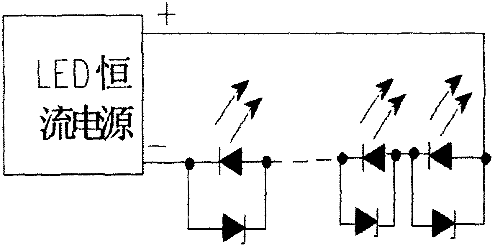
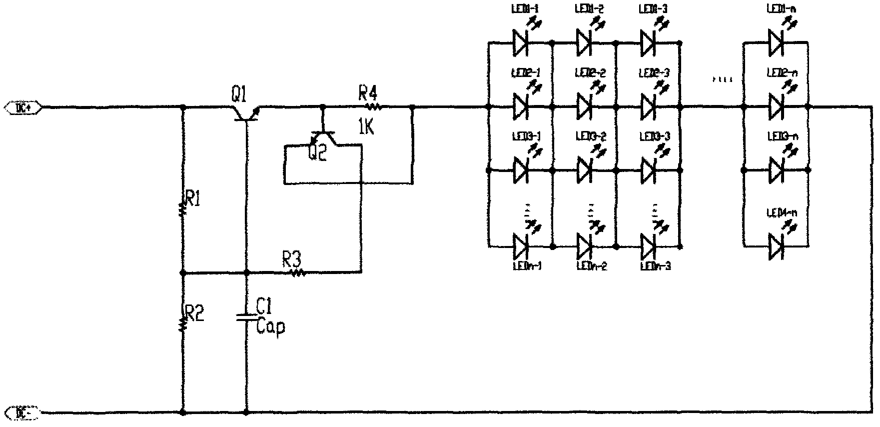
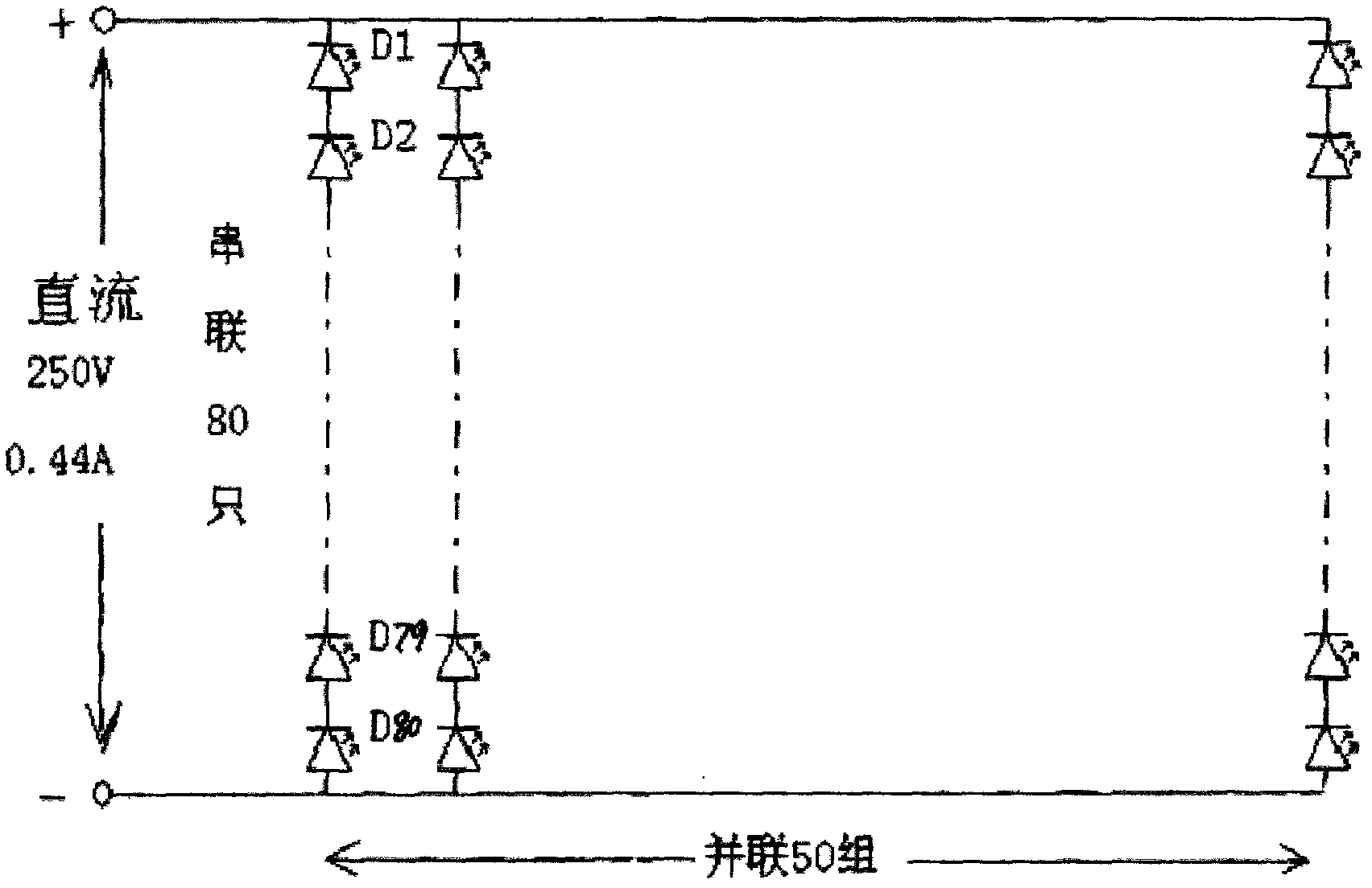
technical field [0001] The invention relates to an LED illuminating lamp, in particular to an AC / DC high-energy-saving, environment-friendly, flow-adjustable LED indoor and outdoor illuminating lamp, which belongs to the lighting field. Background technique [0002] Since the first batch of LEDs entered the market in 1968, it has been more than 40 years. The existing technology and its technical defects are described as follows: [0003] Prior art 1: CN201875511U, describes the use of DC constant current power supply, connected in series with multiple LED lighting, as attached figure 1 shown. Such setting can only be a non-adjustable fixed value because the current is limited by the constant current power supply, and the luminous efficiency is relatively low, so far it has not been able to reach 130 lumens / watt. [0004] Prior art 2: CN201919223U, describes the use of a DC constant current power supply, connected in parallel to multiple LED lighting, as attached figure 2...

Claims


Application Information

Patent Timeline
IPC IPC(8): H05B37/02
Inventor 周胜祥周海园周海波
Owner 周胜祥
Why Eureka
Try Eureka