Method of controlling a powered air purifying respirator

A technology for air purification and respirators, which is applied in the direction of respiratory protection containers, breathing masks, respiratory protection devices, etc., and can solve problems such as damage to the integrity of isolation suits

Inactive Publication Date: 2012-09-12
3M INNOVATIVE PROPERTIES CO
View PDF6 Cites 14 Cited by
  • Summary
  • Abstract
  • Description
  • Claims
  • Application Information

AI Technical Summary

Problems solved by technology

The user may often not notice if the

Method used


Image

  • Method of controlling a powered air purifying respirator
  • Method of controlling a powered air purifying respirator
  • Method of controlling a powered air purifying respirator

Examples


Embodiment Construction

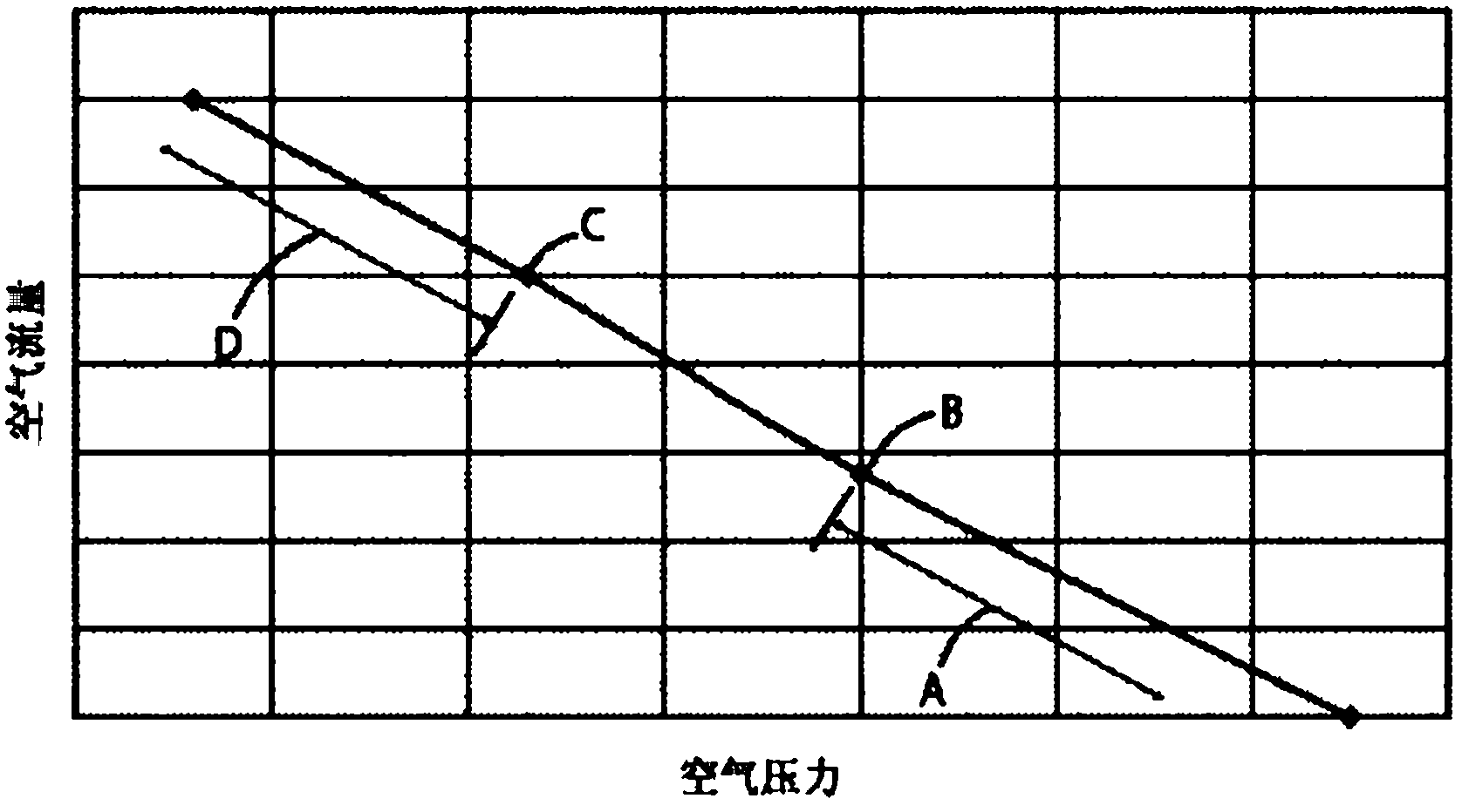
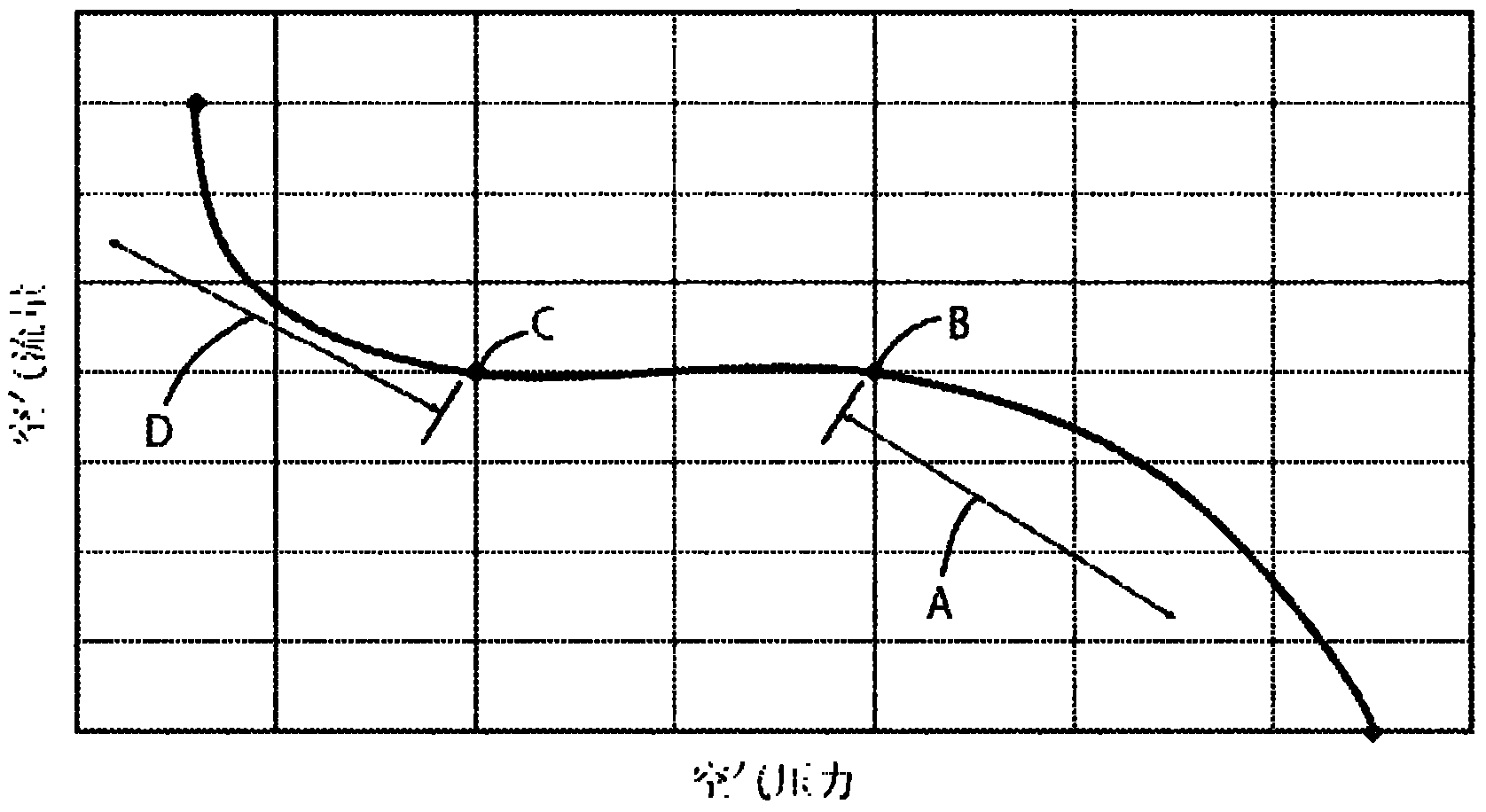
[0024] Many electronic control units deliver constant current or constant voltage to the motor so that the air flow from the blower system is not affected during PAPR operation as the battery is depleted. Certain electronic control units control the power supplied to the motor with the goal of maintaining a substantially uniform volume of air flow from the blower system.

[0025] Such an electronic control unit typically compensates for changes in the battery voltage as dust or particulate matter clogs the filter, and also compensates for changes in the pressure drop across the filter. The term "volume air flow" refers to the volume of air supplied to the user at any one time, not the mass of air supplied to the user at any one time.

[0026] Three types of control systems: constant current, constant voltage and volumetric air flow, using parameter sets with a defined operating range, for the electrical characteristics of the motor (voltage across the motor, current through th...


PUM


Abstract

A method of controlling a powered air purifying respirator blower system to detect a low air pressure high airflow event is disclosed. The blower system comprises a fan powered by an electric motor, controlled by an electronic control unit for delivering a forced flow of filtered air to a user. The electronic control unit has a plurality of data points representing events defining an acceptable operating range in terms of different characteristics of the blower system stored therein. The method comprises sampling a characteristic that represents the operating condition of the blower to obtain a sampled data point; comparing the sampled data point and the stored data point representing a low air-pressure high airflow event, for the same characteristic; repeating the sampling during a fixed time period, and if the comparing step indicates the low air-pressure high airflow event has been reached for the majority of the time period; activating an alarm. Use of a respirator employing the method to deliver a forced flow of filtered air to a contained user environment is also disclosed.

Description

[0001] The present invention relates to a method of controlling a blower system for a powered air purifying respirator (PAPR), and in particular to detecting low air pressure high air flow events. Background technique [0002] Respirators are commonly used by workers when working in areas where dust, fumes or gases are known to be, or may be, potentially hazardous or harmful to health. A common type of respirator used in such environments is the Powered Air Purifying Respirator (PAPR). PAPRs have a blower system that includes a fan driven by a motor to deliver a forced flow of air to the respirator user. The turbine unit typically includes a housing, which typically houses the blower system, and is adapted to connect the filter to the blower system. [0003] Air is drawn by the blower system through the filter and from the turbine unit through the breathing tube to either the mask or the user's environment, such as a mask, helmet, shield or gown (where The user is in an envi...

Claims


Application Information

Patent Timeline
IPC IPC(8): A62B7/10A62B18/00A62B9/00
CPCA62B7/10A62B9/006A62B18/006A62B18/04
Inventor 特伦斯·M·塞耶斯本特·卡尔曼安德鲁·墨菲德斯蒙德·T·柯伦
Owner 3M INNOVATIVE PROPERTIES CO
Why Eureka
Try Eureka