Open-bore magnet for use in magnetic resonance imaging

A magnetic resonance and magnet technology, which is used in magnetic resonance measurement, magnetic objects, superconducting magnets/coils, etc., can solve the problem of inability to obtain SNR of high-field MRI systems, and achieve the effect of keeping magnets safe and cost-effective

Active Publication Date: 2012-09-12
NMR HLDG NO 2
View PDF11 Cites 11 Cited by
  • Summary
  • Abstract
  • Description
  • Claims
  • Application Information

AI Technical Summary

Problems solved by technology

[0017] The low-field nature of the current smaller MRI systems on the market is a major disadvantage of their use
According to the American College of Rheumatology, for images of similar spatial resolution, low-field MRI systems cannot achieve the SNR of high-field MRI systems

Method used


Image

  • Open-bore magnet for use in magnetic resonance imaging
  • Open-bore magnet for use in magnetic resonance imaging
  • Open-bore magnet for use in magnetic resonance imaging

Examples


Embodiment 1

[0078] Example 1 (1.5T whole body magnet)

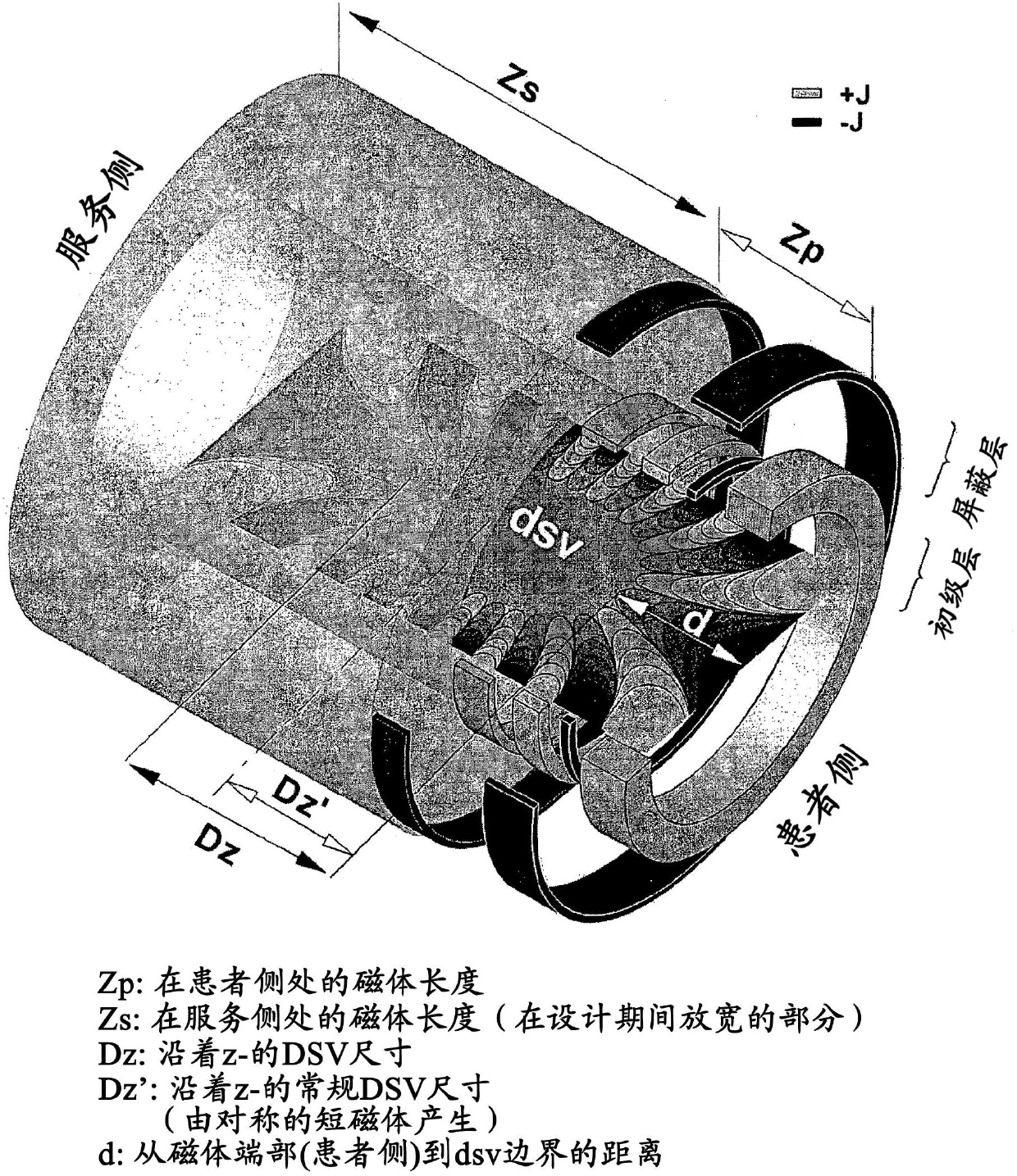
[0079] exist Figure 4 This example schematically shown in shows a superconducting magnet according to an embodiment of the invention. Broadly summarized, the magnet uses 13 coils and has a cold hole length and cold hole inner radius of approximately 1.34 and 0.49 meters, respectively. More importantly, the shortest distance between the cold hole magnet end and the edge of the dsv is only 0.36 m, which is difficult to achieve with other coil configurations. In this example, the axial distance between the center of the magnet and the center of the imaging is 1.2 cm. On the primary winding of the magnet, all coils are wound in the same direction (ie, have the same polarity), except for the second coil from the end. These coils are wound in the opposite direction (ie have opposite polarity) to all other coils on the primary winding.

[0080] The coil block on the primary winding has an asymmetrical electromagnetic topology with resp...

Embodiment 2

[0086] Example 2 (3T limb magnet (version a, b))

[0087] exist Figure 10 and 15 This example, schematically shown in , shows a 3T superconducting magnet design using structures according to the second and third embodiments of the invention.

[0088] Such as Figure 10 As shown, in design version "a", the coil structure is less than 55 cm in total length, while a uniform dsv is produced: 23.5 cm along the axial direction, and 7.5 cm in the radial direction, where the uniformity of the dsv is in the The change in volume is less than 5ppm. On the patient side of the primary layer, the coil next to the end coil has the opposite polarity to all other coils in the primary coil set. The six middle coils in this embodiment are located in the central region of the magnet. There is no negative coil next to the end coil on the service side. In this example, the axial distance between the center of the magnet and the center of the imaging is 1.2 cm. The coil structure again offer...


PUM

PropertyMeasurementUnit
lengthaaaaaaaaaa
lengthaaaaaaaaaa
lengthaaaaaaaaaa

Abstract

A magnetic resonance system is provided which employs a shielded, electromagnetically asymmetric and low-stress magnet to produce a superior sized imaging region close to the patient side. The magnet has a double layered configuration. In the primary layer, the magnet includes at least two strongest coils at two ends of the magnet (end coils), which carry current in the same direction. The magnet may include at least one coil close to the end coils which carries current in a direction opposite to that of the end coils. The magnet employs a plurality of smaller sized coils (4-7, relative to the large end-coils) in the central region of the primary layer, and these coils are located asymmetrically relative to the imaging region centre. The magnet is shielded by a plurality (1-5) of shielding coils, which carry current in a direction opposite to that of the end-coils at primary layer. Compared with conventional short-bore magnets, the magnet of the invention offers an accessible imaging region with significantly enlarged imaging region, and it can be used in, for example, body-part or whole-body imaging.

Description

field of invention [0001] The present invention generally relates to magnets for use in magnetic resonance imaging ("MRI") applications for generating magnetic fields. In particular, the present invention aims at generating a substantially uniform magnetic field (B 0 Field) of virtually short shielded asymmetric superconducting magnets for use in MRI applications, although the invention is not limited thereto. Such magnets are well suited for use in whole body magnetic resonance imaging and in specialist magnetic resonance imaging, for example when producing images of joints and other extremities of a subject. Background of the invention [0002] Magnetic resonance imaging was introduced in the 1980s and has grown into a major global imaging modality with current sales worldwide of approximately 3,000 scanners per year. [0003] The success of clinical MRI depends on the generation of strong and pure magnetic fields. The main specification of the static field in MRI is th...

Claims


Application Information

Patent Timeline
Patent Type & Authority Applications(China)
IPC IPC(8): G01R33/3815G01R33/20A61B5/055H01F6/00
CPCG01R33/3815H01F6/06A61B5/055G01R33/20H01F6/00
Inventor 刘峰日宇·魏斯图尔特·克罗泽
Owner NMR HLDG NO 2
Why Eureka
Try Eureka