Microelectrode array architecture

A micro-electrode array and micro-electrode technology, applied in electrical digital data processing, laboratory containers, instruments, etc., can solve the problems of difficulty in implementing and lacking hierarchical design methods

Inactive Publication Date: 2012-09-19
王崇智 +3
View PDF11 Cites 39 Cited by
  • Summary
  • Abstract
  • Description
  • Claims
  • Application Information

AI Technical Summary

Problems solved by technology

The difficulty with the hierarchical approach is that the lack of standard fabrication techniques and d...

Method used


Image

  • Microelectrode array architecture
  • Microelectrode array architecture
  • Microelectrode array architecture

Examples


Embodiment Construction

[0096] The microelectrode array structure is applicable to other digital microfluidics technologies such as dielectrophoresis (DEP) based technologies, but for discussion purposes below, various embodiments of the invention will be described using EWOD technology.

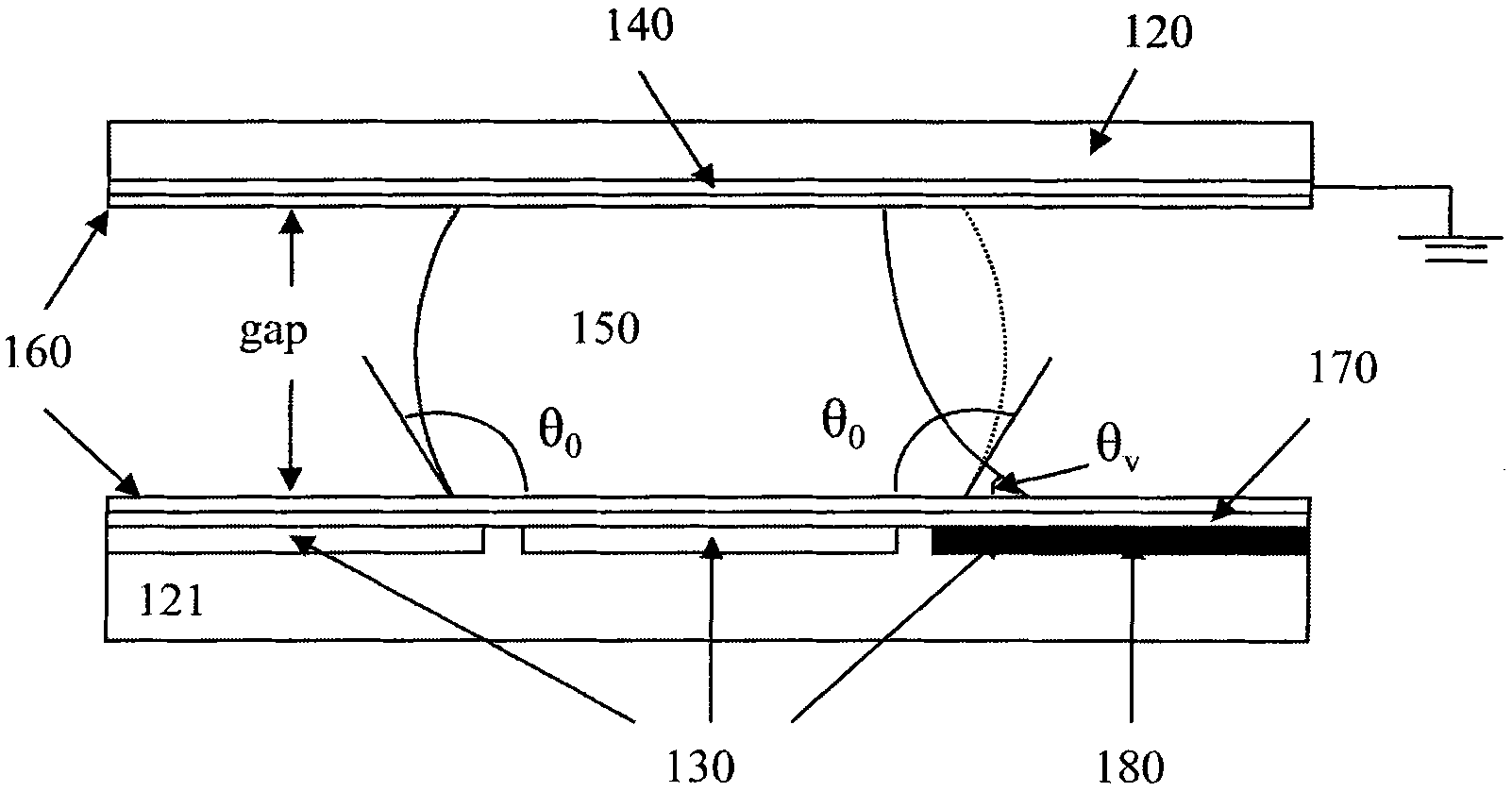
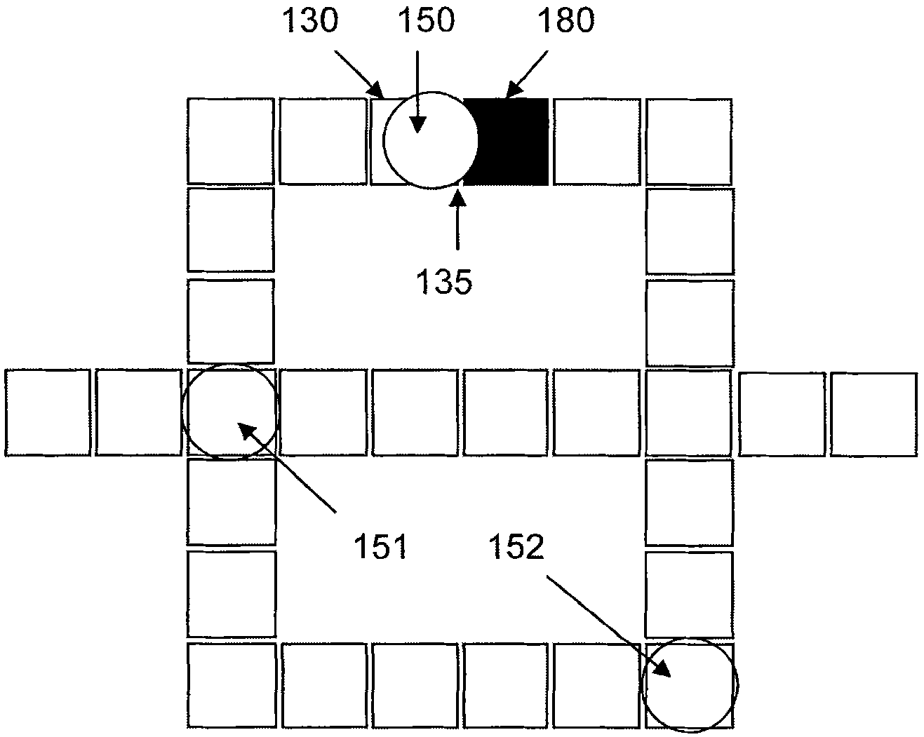
[0097] EWOD-based devices are commonly used to manipulate droplets by exciting them with interfacial tension gradients across the gap between adjacent electrodes. The design of the electrodes includes the desired shape, size of each electrode and the gap between each two electrodes. In droplet manipulation based on EWOD-based LOC layout design, the droplet path is usually constructed by multiple electrodes connecting different regions of the design.

[0098] exist Figure 1AA conventional electrowetting microactuator structure is shown in (shown on a smaller scale for illustrative purposes only). The EWOD-based digital microfluidic device includes two glass plates 120 and 121 parallel to each other. The bottom pl...


PUM


Abstract

The invention discloses a microelectrode array architecture, concretely a device of the microelectrode array architecture, comprising: (a) a bottom plate comprising an array of multiple microelectrodes disposed on a top surface of a substrate covered by a dielectric layer; wherein each of the microelectrode is coupled to at least one grounding elements of a grounding mechanism, wherein a hydrophobic layer is disposed on the top of the dielectric layer and the grounding elements to make hydrophobic surfaces with the droplets; (b) a field programmability mechanism for programming a group of configured-electrodes to generate microfluidic components and layouts with selected shapes and sizes; and, (c) a system management unit, comprising: a droplet manipulation unit; and a system control unit.

Description

[0001] Cross References to Related Applications [0002] This application is incorporated by reference into co-pending U.S. Patent Application No. "Droplet Manipulations on EWOD Microelectrode Array Architecture," filed February 17, 2011. 13,029,137 , a joint pending US Patent Application No. entitled "Field-Programmable Lab-on-a-Chip and Droplet Manipulations Based on EWOD Micro-Electrode Array Architecture" filed on February 17, 2011 13,029,138 and co-pending U.S. Patent Application No. "Microelectrode Array Architecture," filed February 17, 2011. 13,029,140 the entire content of . technical field [0003] The present invention relates to microelectrode array structures, and more particularly, the present invention relates to the manipulation of independently controllable discrete liquid droplets, including (but not limited to) microfluidic systems and methods based on electrowetting on media. The present invention provides scalable system architectures based on arrays of ...

Claims


Application Information

Patent Timeline
IPC IPC(8): B01L3/00G06F17/50
Inventor 王崇智何庆延黄大卫王文生
Owner 王崇智
Why Eureka
Try Eureka