Special shape correcting machine for integrated-casting non-welding chute

A calibrating machine, no welding technology, applied in the field of mechanical design, can solve the problems of large welding internal stress, inability to effectively remove welding stress, open welding, falling off, etc., to improve quality, improve overall docking performance and interchangeability Effect

Active Publication Date: 2012-09-19
山东冀凯装备制造有限公司
View PDF6 Cites 4 Cited by
  • Summary
  • Abstract
  • Description
  • Claims
  • Application Information

AI Technical Summary

Problems solved by technology

Because the material of each component of the cast-welded chute is inconsistent, the depth of the welding joint is high, and the maximum length is 1.75 meters, which often leads to considerable internal stress in welding; at the same time, the shape of the chute is complex and large, and the welding stress cannot be effectively removed after welding. Accidents that affect production, such as welding and falling off, often occur in the center; in addition, the difference in wear resistance is also very large, especially when the middle plate, groove side, and shovel plate are used, frequent well maintenance is required, which seriously affects production efficiency and production costs.
Therefore, the current production of the chute adopts integral casting for one-time molding, and in the process of integral casting and heat treatment of the chute, due to the complexity of the process, it is easy to cause the baffle groove side, scraper groove side, middle plate, bottom cover plate, square The orifice plate is deformed, which leads to problems such as height misalignment between the middle plates of adjacent chutes, uneven end faces of the side of the baffle plate and the side of the shovel plate, and difficulty in docking of concave-convex joints after the ground of the chute is docked.

Method used


Image

  • Special shape correcting machine for integrated-casting non-welding chute
  • Special shape correcting machine for integrated-casting non-welding chute

Examples


Embodiment Construction

[0016] The present invention will be described in further detail below in conjunction with the accompanying drawings and specific embodiments.

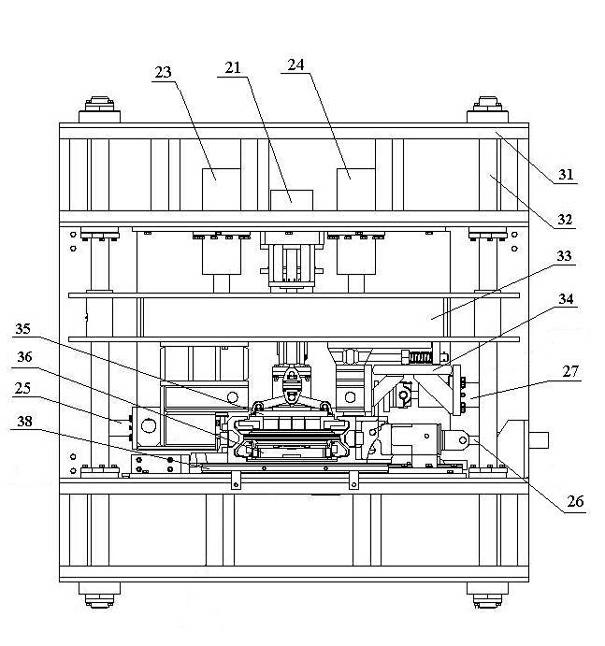
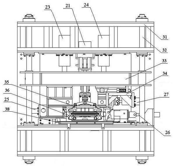
[0017] A special calibrating machine for whole cast non-welding chute, which is applied to the calibrating treatment of the middle chute in the production process, and its structural diagram is as follows figure 1 shown. It includes an electric control system, a hydraulic system and a calibration mechanism. The electric control system is connected with the hydraulic system to control the operation of the hydraulic system; the hydraulic system is connected to the calibration mechanism to provide working power for the calibration mechanism.

[0018] The calibration mechanism in this embodiment is provided with a space for placing the casting in the middle groove, and the calibration mechanism is provided with a main body frame 31, a fixed guide column 32, a movable mold 33, a square hole plate calibration mechanism, and a middle plate a...


PUM


Abstract

The invention discloses a special shape correcting machine for an integrated-casting non-welding chute, which is applied to shape correcting treatment in the production process of the chute. The special shape correcting machine comprises an electric control system, a hydraulic system and a shape correcting mechanism, wherein the electric control system is connected with the hydraulic system which is connected with the shape correcting mechanism; and the shape correcting mechanism comprises a main body frame, as well as fixed guide columns, a movable die, a square-hole plate shape correcting mechanism, a middle-plate upper pressing die, a middle-plate lower pressing plate, a shovel-plate groove-side shape correcting mechanism and a bottom-sealing-plate shape correcting cushion plate, which are arranged on the main body frame. The special shape correcting machine disclosed by the invention has the advantages that the shape of the chute can be corrected in the production process, the whole butting performance and the exchange performance of the product are greatly improved, the problem that the deformation of a large complex casting has an influence on the butting and exchange is thoroughly solved, and the quality of the product is wholly improved.

Description

technical field [0001] The invention relates to a calibration tool in the field of mechanical design, in particular to a calibration machine for calibrating the shape of a fully cast non-welding chute. Background technique [0002] The chute is the guiding mechanism and supporting mechanism for the traction chain and cargo of the scraper conveyor. It is the main component of the scraper conveyor and is most frequently used in coal mines. It mainly includes middle chute, transition chute, adjusting chute, connecting chute and rear chute, etc. The application of chute greatly facilitates the position change of items. Because the material of each component of the cast-welded chute is inconsistent, the depth of the welding joint is high, and the maximum length is 1.75 meters, which often leads to considerable internal stress in welding; at the same time, the shape of the chute is complex and large, and the welding stress cannot be effectively removed after welding. Accidents th...

Claims


Application Information

Patent Timeline
Patent Type & Authority Applications(China)
IPC IPC(8): B21D1/00
Inventor 郝行章李鸿
Owner 山东冀凯装备制造有限公司
Why Eureka
Try Eureka