Bidirectional self-centering power chuck

A self-centering and chucking technology, applied in the direction of the chuck, can solve the problems of affecting the machining accuracy of the workpiece and easy deformation, and achieve the effects of improving machining accuracy, convenient machining and high pressure.

Inactive Publication Date: 2012-09-19
贺自清
View PDF8 Cites 8 Cited by
  • Summary
  • Abstract
  • Description
  • Claims
  • Application Information

AI Technical Summary

Problems solved by technology

[0002] At present, the jaws of self-centering manual chucks or self-centering power chucks used on various machine tools can only move in one direction at the same time, that is, It is only the clamping movement of the jaws to the center of the circle or the stretching movement of the jaws away from the center of the circle, and some thin-walled workpieces are easily deformed whether they are clamped alone or stretched alone, which affects the machining accuracy of the workpiece

Method used


Image

  • Bidirectional self-centering power chuck
  • Bidirectional self-centering power chuck
  • Bidirectional self-centering power chuck

Examples


Embodiment Construction

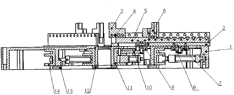
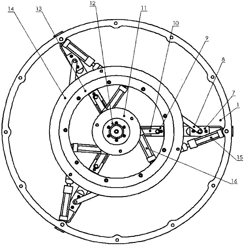
[0026] exist figure 1 , 2 In the first embodiment, the inner turret 11 and the outer turret 14 have the same structure and different diameters, and they are respectively set on the concentric inner pipe wall and the middle pipe wall under the chuck body 1, the inner flange 12, the outer flange Lan 13 is respectively fixed on the inner pipe wall and the middle pipe wall below the chuck body 1 and limits the axial displacement of the inner turret 11 and the outer turret 14 respectively. On the outer tube wall, the cylinder rod is hinged on the outer turret 14, the cylinder body of the inner oil cylinder 16 is hinged on the middle tube wall of the chuck body 1, the cylinder rod is hinged on the inner turret 11, and the inner jaws 3 are used The inner jaw pin 4 is fixed on the inner jaw seat 2, the inner jaw seat 2 is installed in the upper chute of the chuck body 1, the outer slider 7 is fixed on the inner jaw seat 2 through the slot hole of the chuck body 1 One end of the oute...


PUM


Abstract

The invention relates to a bidirectional self-centering power chuck, which comprises a chuck body, an inner clamping claw base, an inner clamping claw, an inner clamping claw pin, an outer clamping claw base, an outer clamping claw, an outer slide block, outer connecting rods, an inner slide block, inner connecting rods, an inner rotating tower, an outer rotating tower, an outer oil cylinder and an inner oil cylinder. According to the power chuck, the straight line motions of inner and outer oil cylinder rods are converted into opposite circular motions of the inner and the outer rotating towers respectively; and through n groups of inner and outer connecting rods, the inner and the outer slide blocks and the inner and the outer clamping claws, the inner and the outer rotating towers drive the inner and the outer clamping claws in match to be in opposite self-centering clamping motion, and thereby a workpiece is pushed and pulled to the center of a circle to be clamped bidirectionally at one same clamping point. Compared with the prior art, the invention has the advantages that the power chuck is high in machining precision, wide in application range and multiple in function.

Description

technical field [0001] The invention relates to a chuck for fixing workpieces, in particular to a bidirectional self-centering power chuck. Background technique [0002] At present, the jaws of self-centering manual chucks or self-centering power chucks used on various machine tools can only move in one direction at the same time, that is, only the clamping movement of the jaws to the center of the circle or the movement of the jaws away from the center of the circle However, some thin-walled workpieces are easily deformed whether they are clamped alone or braced alone, which affects the machining accuracy of the workpiece. Contents of the invention [0003] The purpose of the present invention is to provide a two-way self-centering power chuck for the above-mentioned shortcomings in the prior art. At the same part of the workpiece, there are not only claws to push the workpiece toward the center of the circle, but also claws to pull the workpiece away from the center of t...

Claims


Application Information

Patent Timeline
Patent Type & Authority Applications(China)
IPC IPC(8): B23B31/103
Inventor 贺自清
Owner 贺自清
Why Eureka
Try Eureka