Intelligent control driver for self-excited retarder and control method

A technology of intelligent control and retarder, applied in the direction of asynchronous induction clutch/brake, electric braking system, electric vehicle, etc., can solve problems such as uneven coil aging, easy deformation of the rotor, and short service life of the controller. Achieve the effects of solving uneven aging, avoiding arcing phenomenon, and prolonging service life

Inactive Publication Date: 2014-05-28
TRW AUTOMOTIVE COMPONENTS SHANGHAI
View PDF5 Cites 0 Cited by
  • Summary
  • Abstract
  • Description
  • Claims
  • Application Information

AI Technical Summary

Problems solved by technology

[0003] 1. Due to the arcing phenomenon caused by the frequent pull-in of the relay, the contacts of the relay are severely ablated, resulting in a short service life of the controller and high maintenance costs
[0004] 2. There are only three gears of "high", "low" and "neutral" for the braking torque gear. During high-grade braking, all excitation coils of the retarder participate in the work, and during low-grade braking, part of the excitation coil of the retarder The coil is involved in the work, the aging of the coil is uneven, and the rotor is prone to deformation, which reduces the service life of the self-excited retarder to a certain extent; the braking torque presents a large step change, which reduces the braking stability and stability of the vehicle. ride comfort
[0007] The self-excited retarder drive controller and its control method disclosed in the patent with the announcement number CN101596870B and the name "self-excited retarder drive controller" solve the problem of the braking torque of the self-excited retarder with the relay as the control element. The defect of the controller, but the design of its thyristor control angle trigger circuit determines that when the thyristor control angle is small, the conduction speed of the thyristor is slow, which reduces the maximum braking torque and work of the self-excited retarder. reliability

Method used


Image

  • Intelligent control driver for self-excited retarder and control method
  • Intelligent control driver for self-excited retarder and control method
  • Intelligent control driver for self-excited retarder and control method

Examples


Embodiment Construction

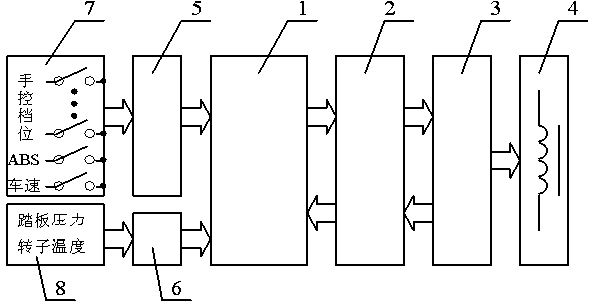
[0017] Such as figure 1 As shown, the present invention includes a microprocessor 1, a switch signal detection circuit 5 and an analog signal detection circuit 6, and several switch signal detection circuits 5 and analog signal detection circuits 6, and a silicon controlled rectifier (SCR) gate trigger pulse circuit 2 are respectively It is connected to the microprocessor 1 through the I / O port; the thyristor gate trigger pulse circuit 2 is connected to the excitation coil drive circuit 3 , and the excitation coil drive circuit 3 is connected to the self-excited retarder body 4 . The switch signals detected by the switch signal detection circuit 5 include switch signals of neutral gear, 1st gear, 2nd gear, 3rd gear, 4th gear and constant speed, ABS switch signal and vehicle speed switch signal; the analog signal detection circuit 6 The detected analog signal includes a brake pedal pressure signal proportional to the brake line pressure and a rotor temperature signal proportion...


PUM


Abstract

The invention discloses an intelligent control driver for a self-excited retarder of a vehicle and a control method. A microprocessor acquires various corresponding signals in real time and calculates a silicon controlled rectifier (SCR) control angle corresponding to the required brake moment; in the positive half period of sine alternating voltage, a voltage comparator U1 outputs positive pulse and a Schmitt trigger U3 outputs negative pulse; one input end of an AND gate U6 receives low electrical level output by a phase inverter U2 and an OR gate U7 outputs the corresponding SCR control electrode trigger pulse; in the negative half period of the sine alternating voltage, the voltage comparator U1 outputs negative pulse and a Schmitt trigger U4 outputs negative pulse; and the AND gate U6 outputs the corresponding SCR control angle signal and the OR gate U7 outputs the corresponding SCR control electrode trigger pulse. Regardless of the dimension of the SCR conductive angle, high-electrical-level signals provide the trigger pulse with steep rising edge and high voltage for the SCR control electrode, and the SCR can be conducted quickly and reliably.

Description

technical field [0001] The invention relates to an auxiliary braking device for road transport vehicles, in particular to a self-excited retarder braking torque control driver installed and used on large and medium tourist buses, public buses and trucks. Background technique [0002] The self-excited retarder is divided into two parts, the power generation device and the retarder device, in the overall structure. When the vehicle decelerates or brakes, the power generation device of the self-excited retarder converts the kinetic energy of the vehicle into sinusoidal alternating current and uses the sinusoidal alternating current to provide excitation current for the excitation coil of the self-excited retarder retarder, which determines the self-excited retarder The control driver of the braking torque of the gearbox is different from the braking torque control driver of the eddy current retarder that uses the DC voltage of the battery as the excitation power supply. At pre...

Claims


Application Information

Patent Timeline
Patent Type & Authority Patents(China)
IPC IPC(8): B60L7/28H02K49/04
CPCY02T10/7241Y02T10/641Y02T10/64Y02T10/72
Inventor 何仁杨效军江蕴梅
Owner TRW AUTOMOTIVE COMPONENTS SHANGHAI
Why Eureka
Try Eureka