
Sliding rail for automobile seats

A car seat and car technology, applied in the direction of movable seats, etc., can solve the problems of sliding rail gap consistency and synchronization difficult to control, small side of the upper guide rail, large adjustment step distance, etc., to achieve good front and rear sliding synchronization, Realize the effect of fine-tuning operation and small clearance of slide rail

Inactive Publication Date: 2012-09-19
JIANGSU ZHONGMING XIANGHE SEIKO
View PDF8 Cites 14 Cited by
  • Summary
  • Abstract
  • Description
  • Claims
  • Application Information

AI Technical Summary

Problems solved by technology

However, the following problems have been exposed in the actual use process: 1. When the slide rail is locked, multiple lock teeth are locked into the locking groove at the same time, so the machining accuracy of the parts is required to be high, and the consistency and synchronization of the slide rail clearance 2. The side of the upper guide rail is small and cannot be used as the installation surface, and there are certain limitations on the installation of the slide rail and the seat frame
However, the following problems have been exposed in the actual use process: 1. Due to the small side of the upper guide rail, it cannot be used as an installation surface, and there are certain limitations in the connection between the slide rail and the seat frame of the car seat; 2. Due to the locking The rows of teeth are placed on both sides and correspond to the lock grooves, so the machining accuracy of the parts is required to be high
[0003] In addition, the current car seat slide rail generally has a large adjustment step, which makes it impossible to meet the best comfort level that the driver wants to achieve ; moreover, the raceways of the upper and lower guide rails of the existing car seat slide rails are on the same plane, which requires high machining accuracy of the parts, and while ensuring the strength, there are certain requirements for the thickness and material of the material, and the cost is relatively low. higher

Method used


Image

  • Sliding rail for automobile seats
  • Sliding rail for automobile seats
  • Sliding rail for automobile seats

Examples


Embodiment Construction

[0024] In order to enable the examiners of the patent office, especially the public, to understand the technical essence and beneficial effects of the present invention more clearly, the applicant will describe in detail below in conjunction with the accompanying drawings in the form of embodiments, but none of the descriptions of the embodiments is a description of the present invention. Restriction of the inventive solution, any equivalent transformation made according to the concept of the present invention which is only in form but not in substance shall be regarded as the scope of the technical solution of the present invention.

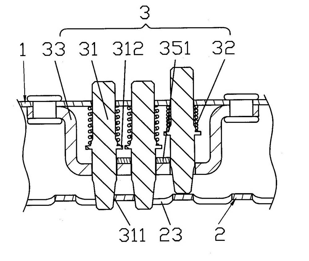
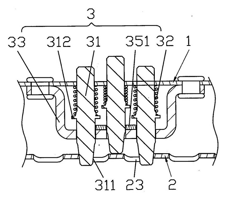
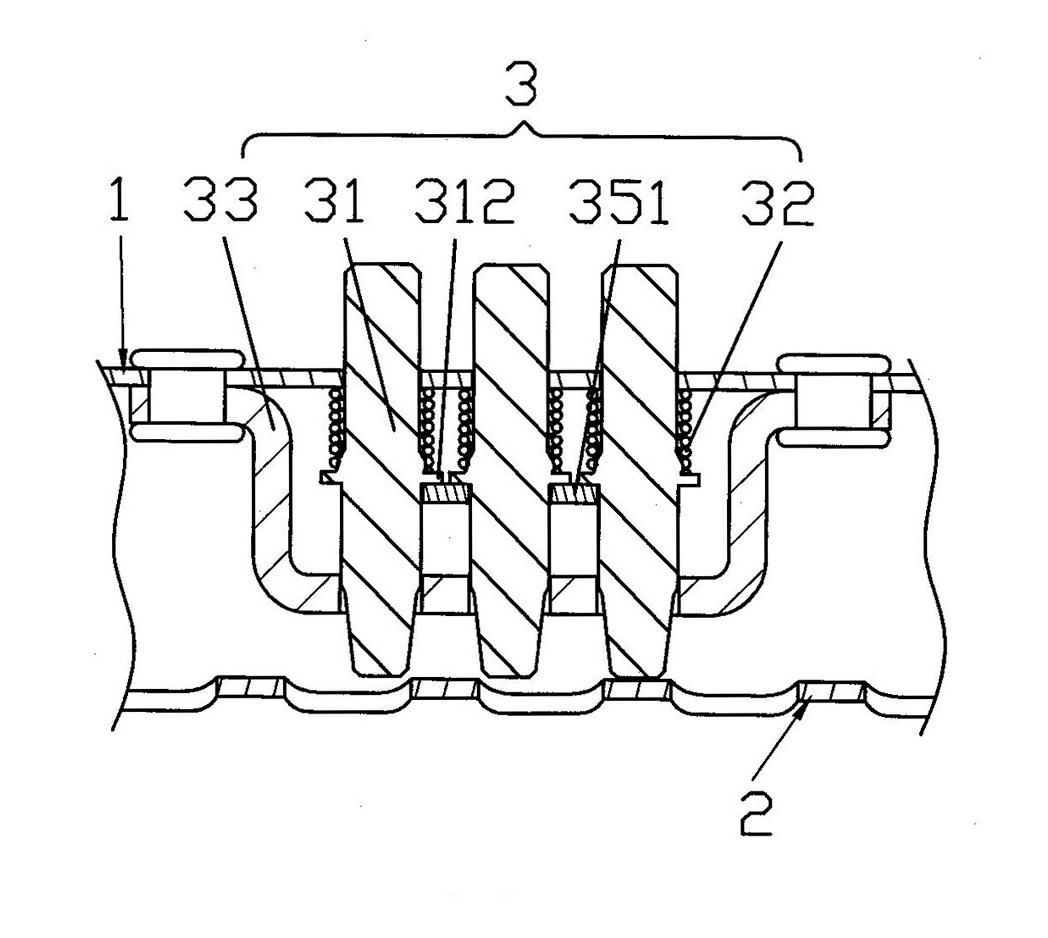
[0025] Please refer to figure 1 and combine figure 2 , image 3 , Figure 4 and Figure 5 , the present invention is a slide rail for car seats, including a lower guide rail 2 for connecting with the car floor, an upper guide rail for connecting with the car seat and slipping on the lower guide rail 2 through the bead frame 4 1, and a locki...


PUM


Abstract

The invention relates to a sliding rail for automobile seats and belongs to the technical field of automobile seat accessories. An upper guide rail is composed of a short folded edge, a long folded edge and an upper installation surface, wherein rollways are respectively formed on the short folded edge and the long folded edge, a first lock pin hole is arranged in the middle of the upper installation surface, and an unlocking block fixing lug, a spring fixing hole and an unlocking rod hole are arranged on the long folded edge. A lower guide rail is composed of a long folded wall, a short folded wall and a lower installation surface, wherein ball grooves are respectively formed on the long folded wall and the short folded wall, and a locking groove is arranged in the middle of the lower installation surface. A locking device comprises a lock pin, a compressed spring, a limit plate, a return spring, an unlocking block, a wrench, an unlocking rod and a connection sleeve. A ball frame is formed by balls, an upper ball positioning roll and a lower ball positioning roll which are all arranged in a containing cavity defined by the rollways and the ball grooves. The sliding rail for automobile seats has the advantages of being high in strength, small in gap, good in synchronism, free of self locking, small in step pitch, few in parts, convenient to assemble and process, low in cost and wide in application range, and an upper sliding lateral surface can also serve as an installation surface.

Description

technical field [0001] The invention belongs to the technical field of vehicle accessories, and in particular relates to a device installed between a seat seat and a vehicle body, which can properly adjust the longitudinal position of a car seat and lock the adjusted position. Background technique [0002] The function of the car seat slide rail is as mentioned above, and it is responsible for changing the front and rear positions of the seat. As such a device, it must be equipped on the car seat. At present, the slide rails that are commonly used on motor vehicle seats in the market are mainly composed of three major components, namely, a lower guide rail used to connect with the car floor, and a lower guide rail used to connect with the car seat and slide through the bead frame. An upper rail on the lower rail, and a locking device for locking the upper rail. This can be obtained in detail through the technical scheme of the previously disclosed Chinese invention patent a...

Claims


Application Information

Patent Timeline
Patent Type & Authority Applications(China)
IPC IPC(8): B60N2/07B60N2/08
Inventor 邹耀忠
Owner JIANGSU ZHONGMING XIANGHE SEIKO
Features
  • Generate Ideas
  • Intellectual Property
  • Life Sciences
  • Materials
  • Tech Scout
  • Unparalleled Data Quality
  • Higher Quality Content
  • 60% Fewer Hallucinations
Learn More