Device for dynamically preparing ice slurry

An ice slurry and dynamic technology, applied in ice making, ice making, lighting and heating equipment, etc., can solve the problems of power and heat consumption, and achieve the effect of increasing ice content rate, avoiding complexity and compact structure

Inactive Publication Date: 2012-09-19
HENAN UNIV OF SCI & TECH
View PDF8 Cites 4 Cited by
  • Summary
  • Abstract
  • Description
  • Claims
  • Application Information

AI Technical Summary

Problems solved by technology

[0007] The purpose of the present invention is to provide a device for dynamically preparing ice slurry, which has solved the problem of power and heat consumption in the prior art because the various components of the ice making device are separated and need to be connected through pipelines

Method used


Image

  • Device for dynamically preparing ice slurry
  • Device for dynamically preparing ice slurry
  • Device for dynamically preparing ice slurry

Examples


Embodiment Construction

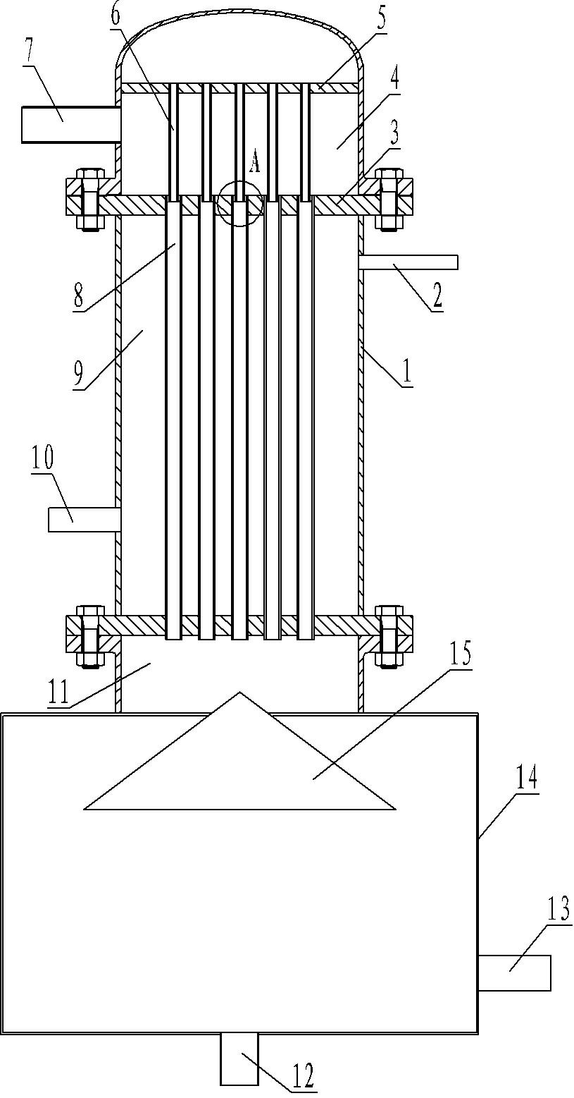
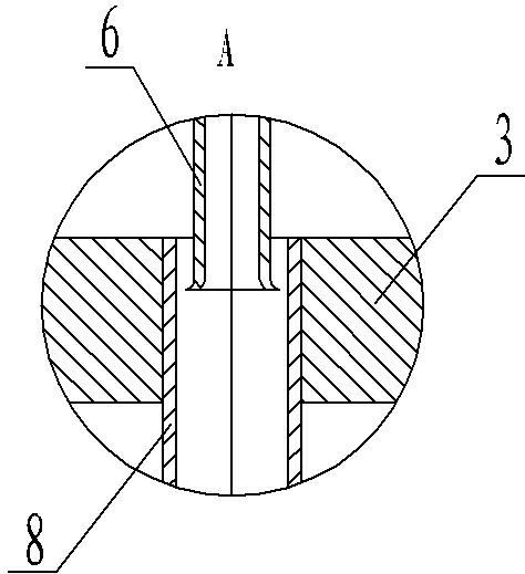
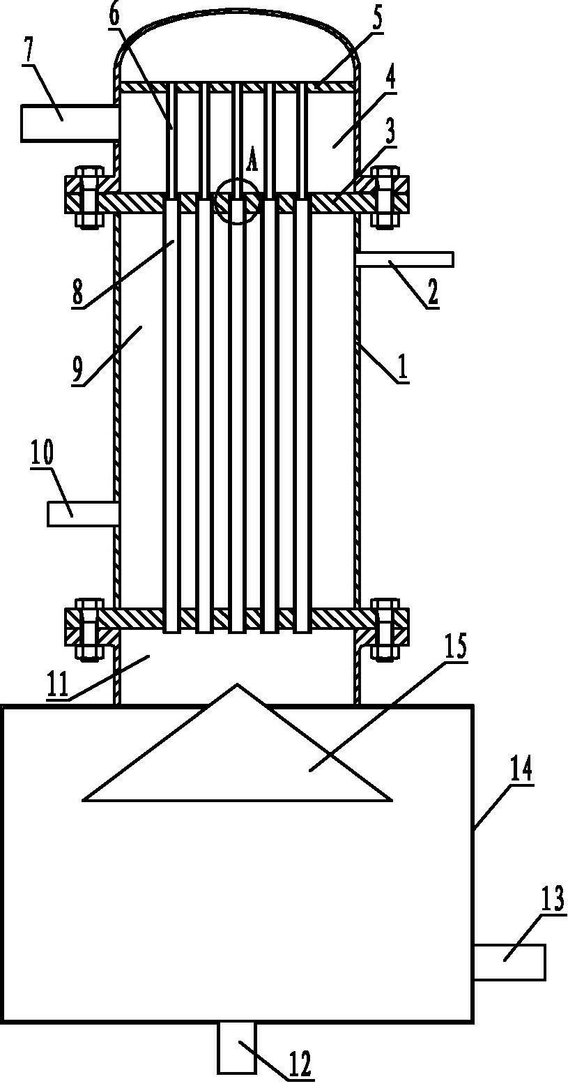
[0026] An embodiment of a device for dynamically preparing ice slurry, in Figure 1~2 Among them, the core component of the device is a tubular heat exchanger, and the outer side of the tubular heat exchanger has a cavity 1, and the cavity 1 is fixedly installed to divide the inner cavity of the cavity 1 into an upper cavity 4 and a middle cavity 9. and the two heat exchange tube fixing plates 3 of the lower chamber 11. Heat exchange tubes 8 are arranged in the middle chamber 9, and the two ends of each heat exchange tube 8 are respectively fixed on the corresponding heat exchange tube fixing plate 3, and the two ends of each heat exchange tube 8 also extend into the upper chamber 4 and the upper chamber respectively. The lower chamber 11 communicates with the upper chamber 4 and the lower chamber 11 respectively. The middle part of the cavity 1 is provided with a refrigerant inlet 10 and a refrigerant outlet 2. Both the refrigerant inlet 10 and the refrigerant outlet 2 are c...


PUM


Abstract

The invention relates to a device for dynamically preparing ice slurry. Two heat exchange tube fixing plates are arranged in a cavity of a tubular heat exchanger of the device, the inner part of the cavity is divided into an upper cavity, a lower cavity and a middle cavity by the two heat exchange tube fixing plates, heat exchange tubes are distributed in the middle cavity, two ends of each heat exchange tube are respectively fixed on the two heat exchange tube fixing plates and are respectively communicated with the upper cavity and the lower cavity, a refrigerating fluid inlet is formed in one of the heat exchange tube fixing plates in the cavity, a refrigerating fluid outlet is formed in the other heat exchange tube fixing plate in the cavity, the refrigerating fluid inlet and the refrigerating fluid outlet are respectively communicated with the middle cavity, a water inlet which is communicated with the upper cavity is formed on the upper part of the cavity, an outlet which is communicated with the lower cavity is formed on the bottom end surface of the cavity, flow guiding columns are fixedly arranged in the upper cavity, lower ends of the flow guiding columns freely extend in ports of the corresponding heat exchange tubes, and the flow guiding columns are in clearance fit with the heat exchange tubes. The upper cavity serves as a reservoir, the lower cavity is used for storing ice, the middle cavity is a heat exchange part, and the device is simple and compact in structure.

Description

technical field [0001] The invention relates to a device for dynamically preparing ice slurry, which is used for preparing ice slurry. Background technique [0002] For a long time, ice has been widely used in air conditioning, fresh-keeping and industrial processing. It is especially worth mentioning that with the rapid development of my country's economy and society, the power supply is tense and the load imbalance of the power grid is becoming more and more prominent. The peak-to-valley difference of daily electricity consumption and the peak-to-valley difference of annual electricity consumption increase. Ice storage has become an important solution and has important energy-saving significance. Although my country has made some progress in the development and application of ice-storage air-conditioning technology, it is still in its infancy and is far from being compared with developed countries such as the United States and Japan. The prospect of researching and promoti...

Claims


Application Information

Patent Timeline
Patent Type & Authority Applications(China)
IPC IPC(8): F25C1/00
CPCY02P60/85
Inventor 梁坤峰徐斌王林段雪涛王全海
Owner HENAN UNIV OF SCI & TECH
Why Eureka
Try Eureka