
Aperture device, video camera and electronic device

A camera and aperture technology, applied in aperture, TV, optics, etc., can solve the problems of increased driving force, high speed (loss of portability, etc.), and achieve the effect of realizing driving force and saving space

Inactive Publication Date: 2012-09-19
NIPPON SEIMITSU SOKKI KK
View PDF5 Cites 5 Cited by
  • Summary
  • Abstract
  • Description
  • Claims
  • Application Information

AI Technical Summary

Problems solved by technology

Thus, for example, when two optical filters are mounted on a common filter support member and moved as in the first prior art, for the movement, the required driving force will increase, so that the movement The high speed (portability) is lost

Method used


Image

  • Aperture device, video camera and electronic device
  • Aperture device, video camera and electronic device
  • Aperture device, video camera and electronic device

Examples


Embodiment Construction

[0060] Hereinafter, embodiments of the present invention will be described in detail with reference to the drawings.

[0061] First, the structure of the camera will be described.

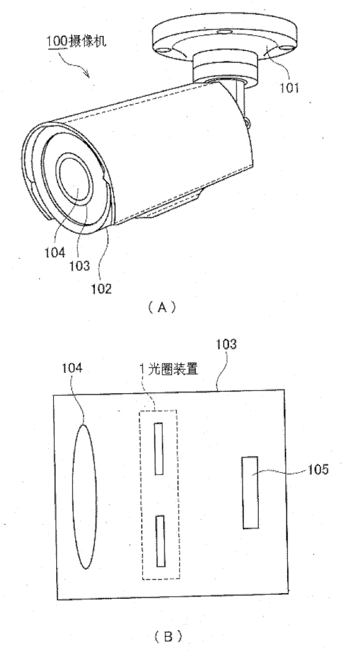
[0062] figure 1 is a diagram showing an example of the structure of a video camera applicable to the present invention, figure 1 (A) is the overall appearance of the camera, figure 1 (B) in (B) is a schematic diagram of the inside of the lens barrel. The illustrated camera 100 is, for example, a surveillance camera installed on a ceiling (or wall, etc.) of a building for the purpose of crime prevention. The camera 100 includes an installation base 101 and a camera body 102 . The mounting base 101 is formed, for example, in a structure that can be fixed to a ceiling portion of a building with screws.

[0063] The camera body 102 includes a barrel portion 103 and an objective lens 104 . An optical system including an objective lens 104 is assembled inside the barrel unit 103 . The objective le...


PUM


Abstract

A light filter switching mechanism is realized in a saved space, the drive force required by switching of an optical filter lens is reduced and high speed of the switching action is realized. A gear part (55) of an arm part (51) integrally rotating with a magnet (50) is engaged with a gear part of a rod part (61) and an action pin (65) of the rod part (61) is embedded with a long hole (67) of a filter lens support part (28) and the embedded state is kept and the rotation of the rod part (61) makes the filter lens support part (28) move along an X direction, so as to switch the arrangement state of the optical filter lenses (26,27). Moreover, relative to an imaginary reference axle (J5) orthogonal with a rotation center axle of the rod part (61) and in parallel to the movement direction X of the filter lens support part (28), a movable terminal of the action pin (65) of the rod part (61) is at a position offsetting one side from the imaginary reference axle (J5) and set in the rotation angle range (Theta3) being less than 180 degree.

Description

technical field [0001] The present invention relates to an aperture device for adjusting the amount of incident light, a video camera and electronic equipment including the aperture device. Background technique [0002] A camera including a surveillance camera incorporates a diaphragm device that adjusts the amount of light incident from the outside (hereinafter referred to as "incident light amount"). The diaphragm device adjusts (quantifies) the amount of incident light by changing the size of the diaphragm opening present on the optical path of the incident light. As a configuration of the diaphragm device, there is a configuration in which the amount of light is adjusted by movement of the diaphragm member. Specifically, as an example of a diaphragm device, a diaphragm device using a pair of diaphragm blades is known (for example, refer to Patent Document 1). [0003] In addition, an imaging element capable of color photography is incorporated in a surveillance camera ...

Claims


Application Information

Patent Timeline
IPC IPC(8): G03B9/02G03B17/14H04N5/238
CPCG02B7/006G03B9/12G03B11/00G02B5/208
Inventor 郡直道竹内慎治户丸崇
Owner NIPPON SEIMITSU SOKKI KK
Learn More