Image forming apparatus

An image and latent image technology, applied in the field of image forming devices, can solve the problems of large suction pump, high cost, large space, etc., and achieve the effect of reducing torque and stable cleaning

Inactive Publication Date: 2012-09-19
SEIKO EPSON CORP
View PDF2 Cites 2 Cited by
  • Summary
  • Abstract
  • Description
  • Claims
  • Application Information

AI Technical Summary

Problems solved by technology

[0013] However, the mesh cleaning device and the suction pump are relatively large and have a complicated structure
Therefore, there is a problem that not only a large space is required but also the cost becomes high

Method used


Image

  • Image forming apparatus
  • Image forming apparatus
  • Image forming apparatus

Examples


Embodiment Construction

[0104] Hereinafter, the form for implementing this invention is demonstrated using drawing.

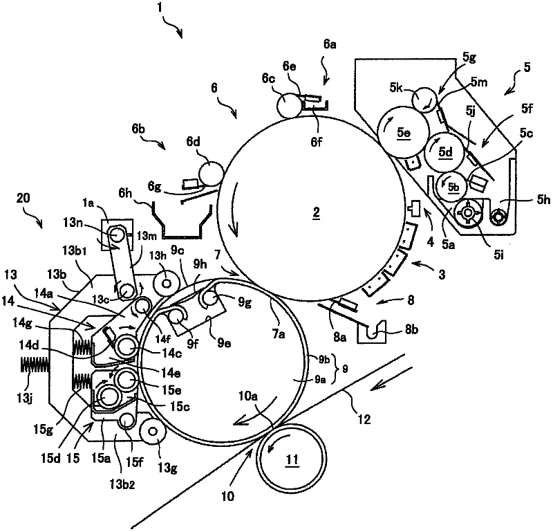
[0105] figure 1 It is a diagram schematically partially showing an image forming apparatus including a first example of an embodiment of the image forming apparatus of the present invention. In the following description, each rotation direction and each movement direction are the directions shown by the arrows in each figure.

[0106] Such as figure 1 As shown, the image forming apparatus 1 of the first example has a photoreceptor 2 as a latent image bearing member that bears an electrostatic latent image. The photoreceptor 2 is driven to rotate counterclockwise by a drive source not shown.

[0107] A charging unit 3 is disposed around the photoreceptor 2 . Further, an exposure unit 4 , a developing unit 5 , a photoreceptor pressing unit 6 , a primary transfer unit 7 , and a photoreceptor cleaning unit 8 are sequentially arranged from the charging unit 3 toward the rotation direct...


PUM


Abstract

An image forming apparatus (1) of the invention includes a carrier solution application roller (15e) that rotates centering on a rotary shaft (15f) and applies a carrier solution to a transfer roller (9) after an image of a liquid developer including toner and the carrier solution is transferred to a transfer medium (12), a transfer roller cleaning roller (14c), supported by a cleaning member support portion (13) through a rotary shaft (14f), which removes toner remaining in the transfer roller (9), and a carrier solution application roller (15e) of which the amount of movement is larger than the amount of movement of the transfer roller cleaning roller (14c) when the cleaning member support portion (13) is rotated. Even when the transfer roller (9) moves, satisfactory cleaning properties are secured without breaking a mutual positional relationship by facilitating mutual positioning between the transfer roller (9) and the transfer roller cleaning roller (14c).

Description

technical field [0001] The present invention relates to the technical field of an image forming apparatus having an image carrying (carrying) roller that rotates in contact with a latent image carrier and that is transferred and developed using a liquid containing toner and a carrier liquid. Toner (also referred to as liquid toner) develops the toner image on the latent image carrier. Background technique [0002] Conventionally, there is known an image forming apparatus in which a toner image formed by developing a latent image formed on a photoreceptor with liquid toner is transferred to a transfer material such as transfer paper, and has the function of toner After the toner image is transferred to the transfer material, the photoreceptor is coated with a carrier liquid to remove the residual toner remaining on the transfer roller (for example, refer to Patent Document 1). [0003] In the photoreceptor cleaning unit of the image forming apparatus described in Patent Docu...

Claims


Application Information

Patent Timeline
Patent Type & Authority Applications(China)
IPC IPC(8): G03G15/00G03G21/00G03G15/16G03G15/10
CPCG03G15/10G03G15/161G03G2215/1657
Inventor 佐佐木努西山和宏奥村尚之高野秀裕井熊健
Owner SEIKO EPSON CORP
Why Eureka
Try Eureka