

Electric energy storage device
A technology for power storage devices and outer packaging, applied to batteries, circuits, electrical components, etc., can solve problems such as rising internal pressure of outer packaging materials, achieve the effect of preventing rupture and improving the conduction state
- Summary
- Abstract
- Description
- Claims
- Application Information
AI Technical Summary
Problems solved by technology
Method used
Image

Examples
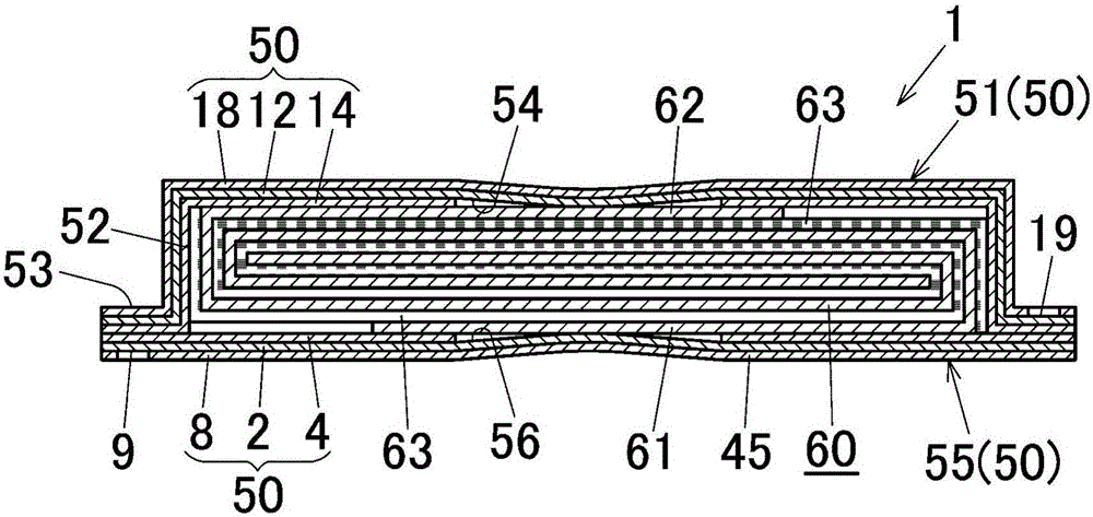
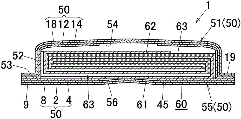
Embodiment 1
[0094] Coating a chemical conversion treatment liquid containing polyacrylic acid, phosphoric acid, chromium and fluorine compounds on both sides of an aluminum foil with a thickness of 40 μm, and drying at 150°C so that the amount of chromium deposited is 3 mg / m 2 .
[0095] One side of the aluminum foil (metal foil layer) after the chemical conversion treatment is coated with a polyester-urethane adhesive. At the time of this application|coating, the part of the edge part of one surface of the aluminum foil was formed as the adhesive agent non-application area by masking process (attaching a masking tape). Then, a biaxially stretched polyamide film (heat-resistant resin layer) having a thickness of 25 μm was pasted on the polyester-urethane adhesive-coated surface. Next, an acid-modified polypropylene-based adhesive was applied to the other surface of the aluminum foil. At the time of this application|coating, the center part of the other surface of the aluminum foil was f...
Embodiment 2
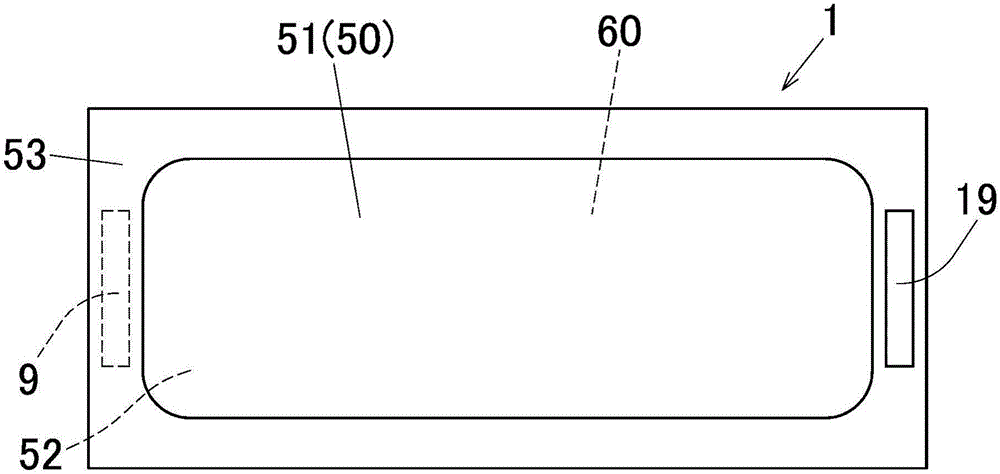
[0099] Prepare two outer packages that are the same as those prepared in Example 1, use these two outer packages, and adopt the method and structure that have been described before to make Figure 4 , 5 The battery of the structure shown. As the electrolyte, the same electrolyte as in Example 1 was used. It should be noted that the angle α formed by the bottom surface and the side surface of the depressed portion 71 was set to 150°, and the depth of the depressed portion 71 was set to 1 mm. In addition, the heat-seal bonding of the heat-sealable resin layers at the peripheral edge portions of the two outer packages was performed in an atmosphere of 1 KPa lower than the atmospheric pressure.
[0100] In the batteries of Examples 1 and 2 obtained by the above-mentioned treatment, the crack prevention properties of the outer casings were evaluated by the following evaluation method.
[0101]
[0102] The internal pressure of each battery was gradually increased by promoting ...
PUM
| Property | Measurement | Unit |
|---|---|---|
| Thickness | aaaaa | aaaaa |
Abstract
Description
Claims
Application Information