
Electromagnetic contractor

An electromagnetic contactor and moving contact technology, applied in the direction of electromagnetic relays, relays, electromagnetic relay details, etc., can solve problems such as arc retention and arc Lorentz force, and achieve increased magnetic flux density and increased Lorentz force. The effect of the Lenz force

Active Publication Date: 2012-09-19
FUJI ELECTRIC FA COMPONENTS & SYST CO LTD
View PDF9 Cites 16 Cited by
  • Summary
  • Abstract
  • Description
  • Claims
  • Application Information

AI Technical Summary

Problems solved by technology

Therefore, there is an unsolved problem that it cannot be ensured that the Lorentz force acting on the arc generated between the fixed contact and the moving contact is sufficiently large when the current is cut off, so that the arc may still remain in the Between the contacts of the fixed contact and the moving contact assembly 110

Method used


Image

  • Electromagnetic contractor
  • Electromagnetic contractor
  • Electromagnetic contractor

Examples


Embodiment Construction

[0074] Below, based on the accompanying drawings ( Figure 1 to Figure 6 B) to explain the embodiment of the present invention.

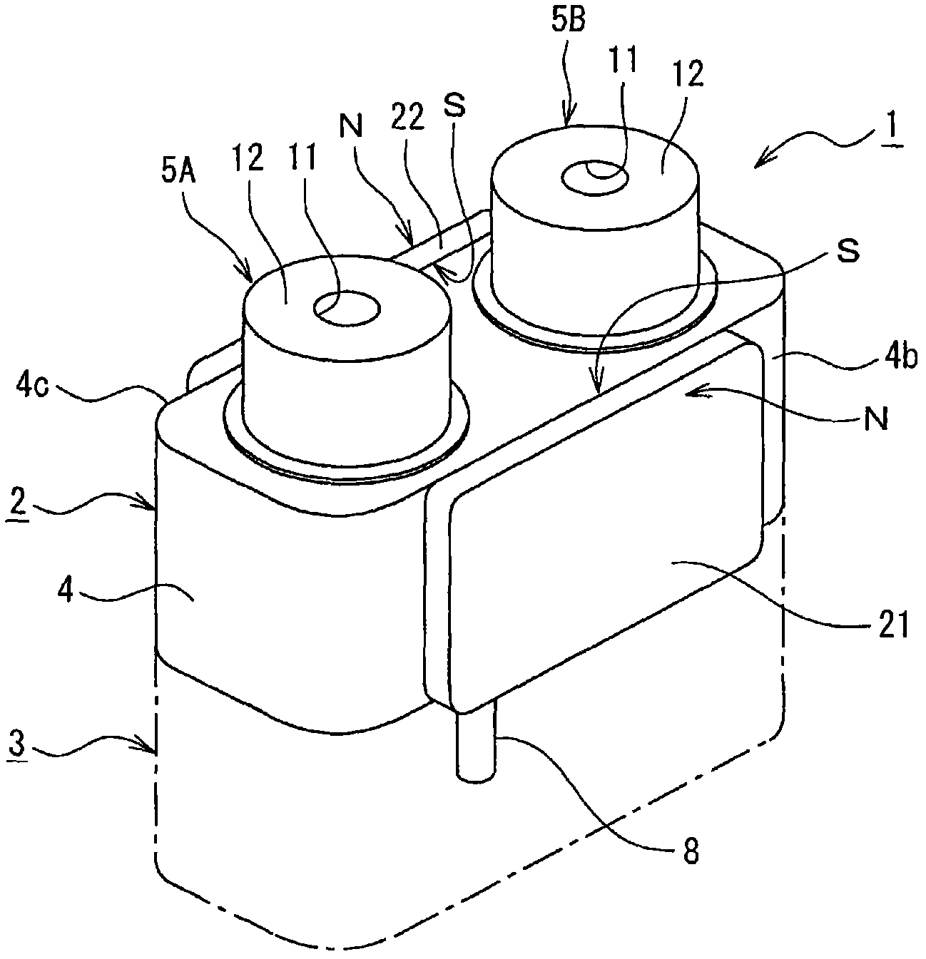
[0075] figure 1 is a perspective view showing a first embodiment of the electromagnetic contactor according to the present invention. exist figure 1 In , reference numeral 1 denotes an electromagnetic contactor constituted by a contact mechanism 2 in an upper part and a driving mechanism 3 in a lower part.

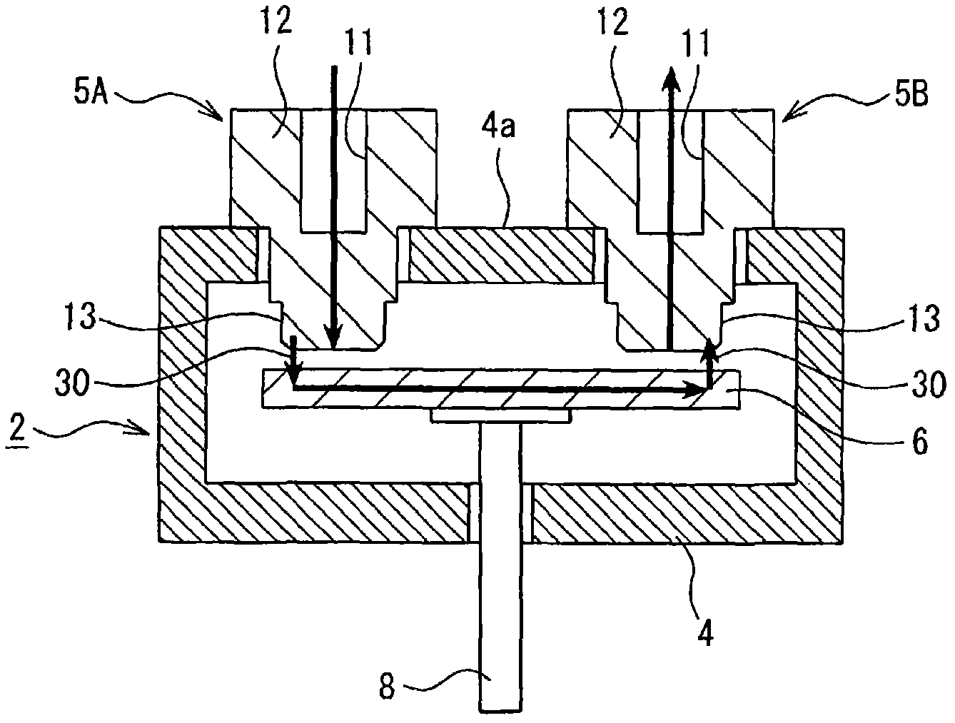
[0076] The contact mechanism 2 is provided with a fixed contact holding case 4, a first fixed contact 5A, a second fixed contact 5B and, for example, figure 2 The moving contact assembly 6 arranged in the fixed contact holding housing 4 is shown in FIG. The fixed contact holding case 4 is formed to have an approximately rectangular solid outer shape with an insulating material. The first fixed contact 5A and the second fixed contact 5B are electrically conductive and are kept at a prescribed distance from each other by the fixed contact ...


PUM


Abstract

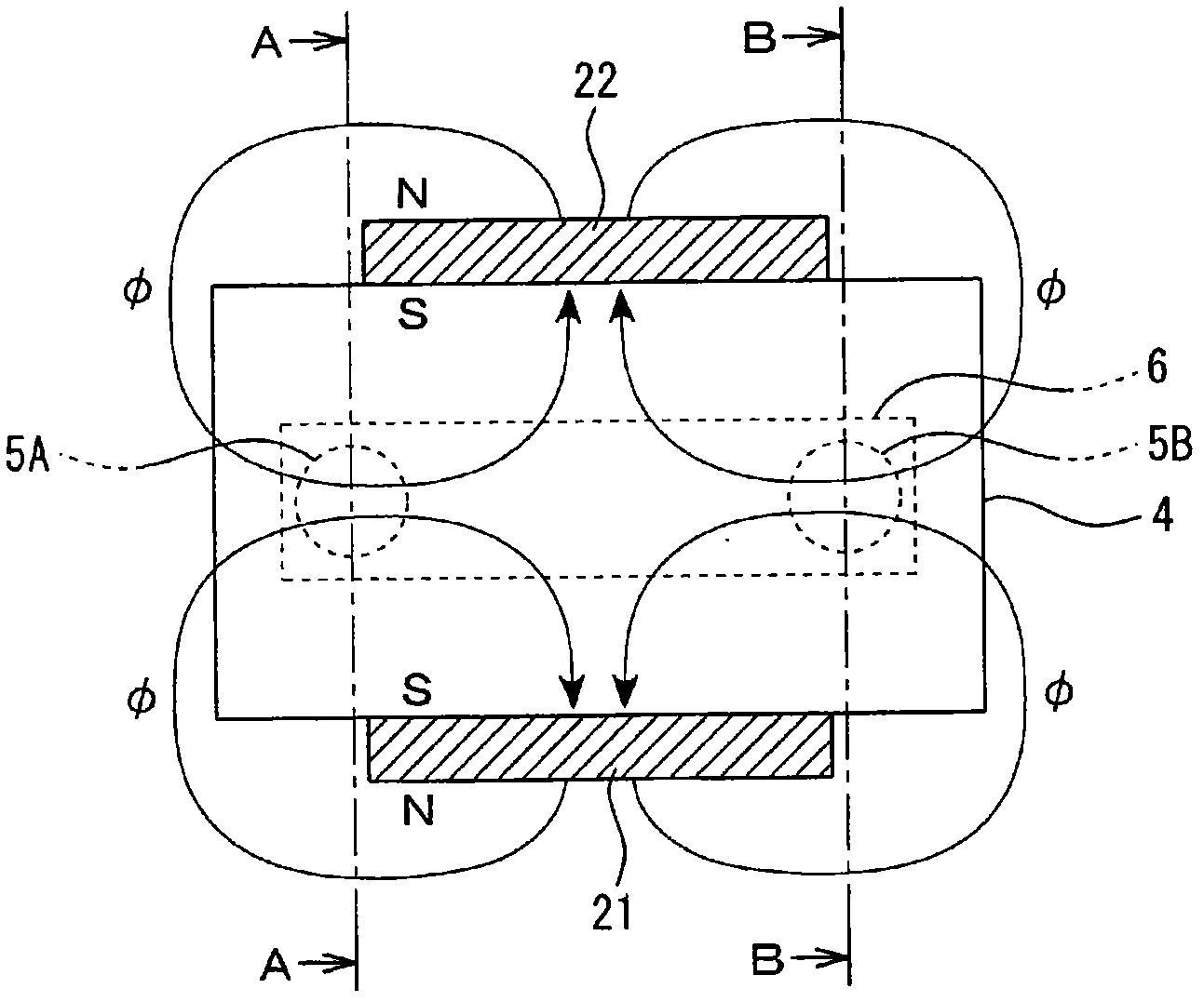
An electromagnetic contactor includes a first stationary contact 5A having a stationary contact portion and a stationary terminal portion for connecting to a power supply; a second stationary contact 5B having a stationary contact portion and a stationary terminal section for connecting to a load; a stationary-contact supporting case 4 supporting the stationary terminal portions of the first and second stationary contacts to protrude the contact support casing, and maintaining a predetermined distance in between; a moving-contact portion contactable to and separable from the stationary contact portion of the first and second stationary contact and arranged in the stationary-contact supporting case; and a pair of arc-extinguishing magnets 21, 22 arranged in parallel to sandwich the moving-contact portion in the longitudinal direction and having same magnetic polarity at opposing magnetic pole surfaces. A driving mechanism 3 drives the moving-contact portion contactable to and separable from the stationary contact portions of the first and second stationary contacts.

Description

technical field [0001] The present invention relates to an electromagnetic contactor inserted into a current path and provided with a fixed contact piece and a moving contact piece assembly, and in particular to an electromagnetic contactor arranged to easily eliminate when opening the fixed contact piece and moving contact piece assembly, that is, when the Electromagnetic contactors that generate arcs when current flows. Background technique [0002] For an electromagnetic contactor used in a high-voltage direct current (DC) power supply circuit of a vehicle such as an electric vehicle or a hybrid vehicle, it has previously been proposed to have Figure 24 and Figure 25 A plunger type electromagnetic relay of the structure shown in (for example, see JP-A-7-235248). The plunger type electromagnetic relay is provided with a pair of fixed contacts 101 and 102 provided on the housing 100 at a prescribed distance, a moving contact holder 105 provided with a pair of moving cont...

Claims


Application Information

Patent Timeline
Patent Type & Authority Applications(China)
IPC IPC(8): H01H50/38H01H50/54
CPCH01H50/546H01H9/443
Inventor 立川裕之磯崎優鹿志村修高谷幸悦中康弘柴雄二
Owner FUJI ELECTRIC FA COMPONENTS & SYST CO LTD
Learn More