
Lid opening and closing device

A technology of opening and closing device and cover body, which is used in transportation and packaging, semiconductor/solid-state device manufacturing, conveyor objects, etc., and can solve problems such as insufficient removal and inability to process wafers.

Active Publication Date: 2012-09-19
TOKYO ELECTRON LTD
View PDF7 Cites 8 Cited by
  • Summary
  • Abstract
  • Description
  • Claims
  • Application Information

AI Technical Summary

Problems solved by technology

As a result, the wafer may not be processed as desired
[0005] In the past, it has been proposed to provide a loading port with a nozzle for ejecting gas on the surface of the cover in order to remove foreign matter, but it is not enough to remove the air inside the cover as described above.

Method used


Image

  • Lid opening and closing device
  • Lid opening and closing device
  • Lid opening and closing device

Examples


no. 1 Embodiment approach

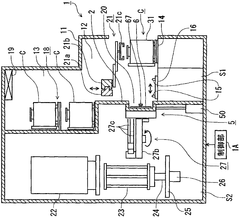
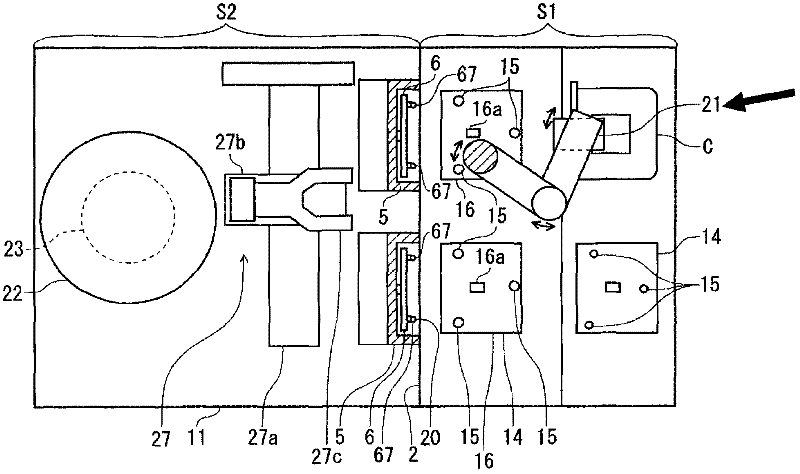
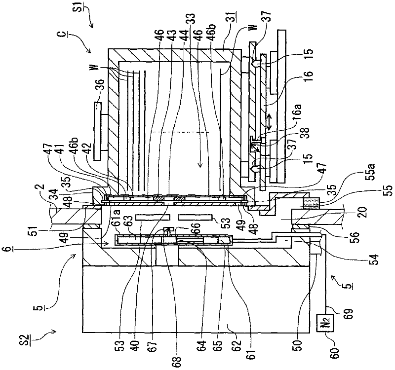
[0042] A vertical heat treatment apparatus incorporating the lid opening and closing device of the present invention will be described. figure 1 It is a longitudinal sectional view of the vertical heat treatment apparatus 1, figure 2 It is a plan view of the vertical heat treatment apparatus 1 . Reference numeral 11 in the figure is a frame body constituting the outer casing of the vertical heat treatment apparatus 1. In the frame body 11, a carrier transport area S1 is formed, which is used for carrying in and out of the apparatus as a storage object to be processed. That is, the carrier C of the container of the wafer W; the wafer transport area S2, which is used as a transfer area, is used to transport the wafer W in the carrier C and carry the wafer W into a heat treatment furnace described later. Carrier C is a FOUP as described above.

[0043]The carrier transfer area S1 and the wafer transfer area S2 are separated by a partition wall 2 . The carrier transport area ...

no. 2 Embodiment approach

[0072] Next, the second embodiment will be described focusing on the points of difference from the first embodiment. Figure 17 The perspective view which shows the removal mechanism 6 of the cover body 41 of this 2nd Embodiment. In this detachment mechanism 6 , instead of the gas discharge port 68 formed in the key 67 , a plurality of gas discharge ports 73 are opened in the plane direction of the facing surface 61 a of the facing plate 61 of the detachment mechanism 6 . The gas ejection port 73 is connected to the internal space 63 of the counter plate 61 . And, the downstream end of the gas supply pipe 69 is opened to the internal space 63 , and the gas injected into the internal space 63 is N 2 Gas is ejected from the gas ejection port 73 in the thickness direction of the opposing plate 61 . That is, in this example, the opposing plate 61 is formed as a shower head-shaped purge gas ejection portion.

[0073] For example, in the state where the key 67 is engaged with the...


PUM


Abstract

The invention provides a lid opening and closing device, which is an opening and closing device for a FOUP. By enabling the edge part of the substrate takeout opening of the FOUP to makes contact with the edge portion of the conveying gateway which is opened and closed by an opening / closing door, and by arranging an opening of a front surface of a FOUP lid in the lid, the engagement of the lid and a FOUP body is released and the lid is held. The conveying gateway is formed on a partition wall configured to divide a FOUP conveying region and a substrate conveying region. The lid opening and closing device compsies an exhaust port configured to discharge therethrough an atmospheric gas from a closed space formed between the FOUP making contact with the edge portion of the conveying gateway and the opening / closing door; and a purge gas injecting part provided in the opening / closing door, the purge gas injecting part configured to enter the internal space of the lid through the opening of the front surface of the lid, to inject a purge gas into the internal space and to discharge an atmospheric gas existing in the internal space into the closed space through another opening of the lid different from the opening.

Description

technical field [0001] The present invention relates to a lid opening and closing device for opening and closing a lid that closes a take-out port of a substrate constituting a part of a FOUP. Background technique [0002] As one of semiconductor manufacturing apparatuses, there is, for example, a vertical heat treatment apparatus that heat-treats a plurality of semiconductor wafers (hereinafter referred to as wafers) in batches. The vertical heat treatment device is set in the atmosphere, and includes: a carrier transport area, which is used to transport a carrier called FOUP for storing wafers; a wafer transport area, which is used to transfer the wafer to The wafer boat used as the substrate holder is transported to the heat treatment furnace; the partition wall is arranged between the carrier transport area and the wafer transport area. In order to make the cleanliness of the wafer transfer area higher than that of the carrier transfer area and prevent the natural oxide...

Claims


Application Information

Patent Timeline
Patent Type & Authority Applications(China)
IPC IPC(8): H01L21/67H01L21/673H01L21/677
CPCH01L21/67772H01L21/67379H01L21/67393
Inventor 菅原佑道
Owner TOKYO ELECTRON LTD
Learn More