Ultrasonic probe and method for manufacturing ultrasonic probe

An ultrasonic and substrate technology, applied in ultrasonic/sonic/infrasonic diagnosis, ultrasonic diagnosis, infrasonic diagnosis, etc., can solve the problems of insufficient pressurization, FPC cannot follow deformation, insufficient rigidity of PCB, etc., and achieve the effect of solving the insufficient pressurization

Inactive Publication Date: 2012-09-26
KK TOSHIBA
View PDF10 Cites 7 Cited by
  • Summary
  • Abstract
  • Description
  • Claims
  • Application Information

AI Technical Summary

Problems solved by technology

When the FPC on the rear surface side is arranged at a position corresponding to the space, the rigidity of the PCB is insufficient for attachment by thermocompression bonding by using a heating tool
As a result, the FPC cannot follow the deformation of the PCB, which reduces the flatness of the thermocompression bonding surface
Therefore, the applied pressure is not enough, and this may cause poor electrical connection

Method used


Image

  • Ultrasonic probe and method for manufacturing ultrasonic probe
  • Ultrasonic probe and method for manufacturing ultrasonic probe
  • Ultrasonic probe and method for manufacturing ultrasonic probe

Examples


Embodiment Construction

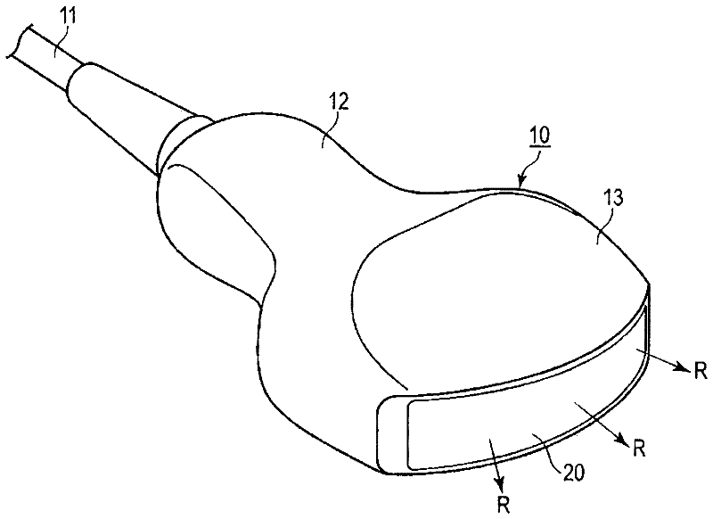
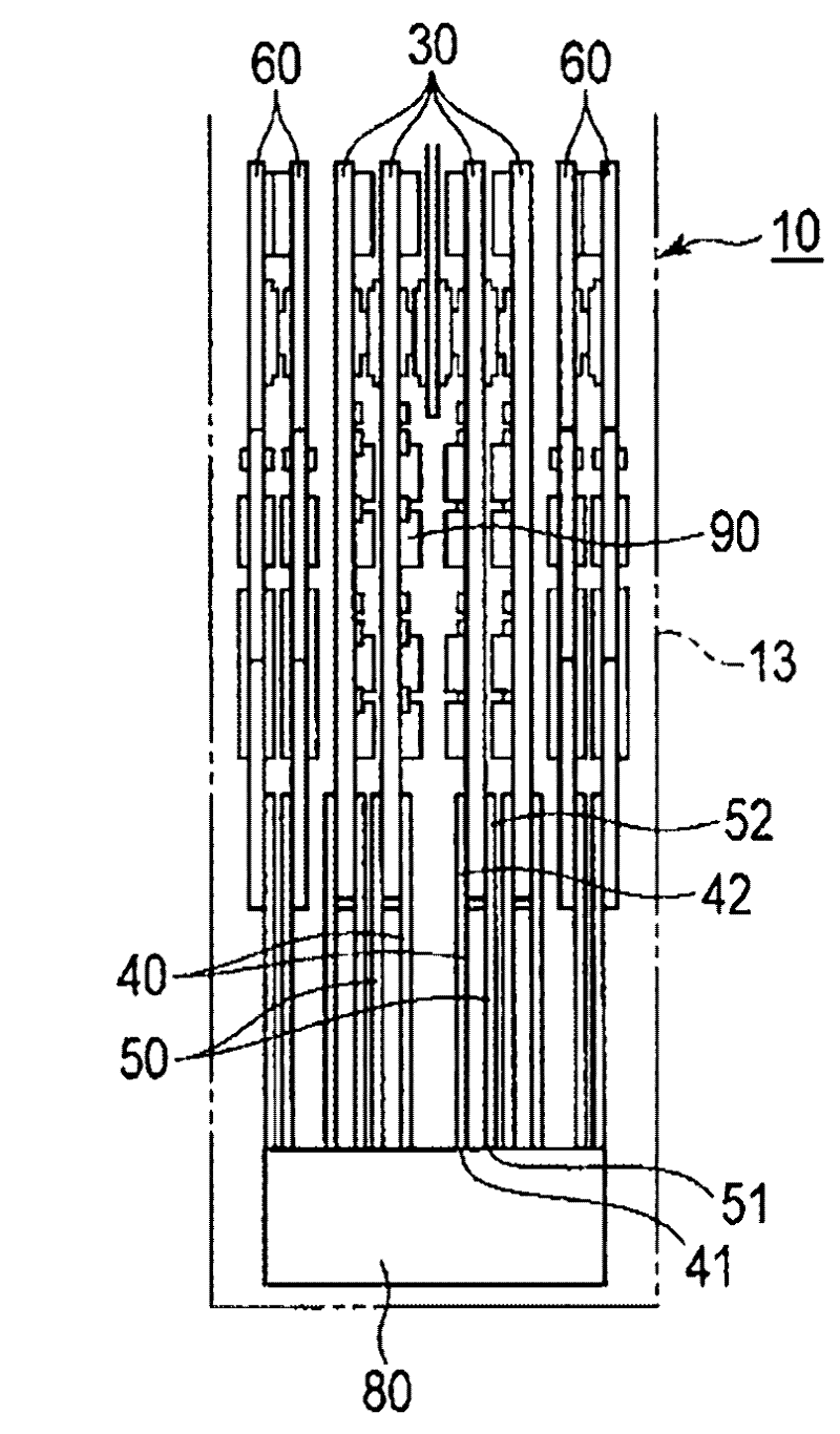
[0026] figure 1 It is a perspective view showing the ultrasonic probe 10 according to the first embodiment. figure 2 It is a cross-sectional view showing essential parts of the ultrasonic probe 10. Figure 3A It is a plan view showing the substrate 30 included in the ultrasonic probe 10. Figure 3B , 3C 3D is a plan view showing the second end 42 of the first FPC 40 connected to the substrate 30. Figure 4A It is a cross-sectional view schematically showing the connection part between the FPC 40 and the substrate 30 of the ultrasonic probe 10. Figure 4B is true Figure 4A A cross-sectional view of the K part indicated by the continuous double dash in the enlarged and displayed section. In these figures, R represents the ultrasonic irradiation direction.

[0027] The ultrasonic probe 10 is a convex 2-D array ultrasonic probe attached to an ultrasonic diagnostic apparatus through a cable 11. The ultrasonic probe 10 includes a handle portion 12 held by an operator and a head 13 tha...


PUM


Abstract

An ultrasonic probe includes, a transducer, a substrate includes electrodes formed on a front surface and a back surface and electronic components, first flexible wire substrates connected in such a manner that a first end is connected to the transducer and a second end is connected to a electrode at a side of the front surface of the substrate, second flexible wire substrates connected in such a manner that a first end is connected to the transducer and a second end is connected to a electrode at a side of the back surface of the substrate, and a dummy materials including the same rigidity and thickness as those of the first flexible wire substrate is arranged at a space, adjacent to a electrode at the side of the front surface of the substrate, corresponding to the second end of the second flexible wire substrate.

Description

[0001] Cross references to related applications [0002] This application is based on the prior Japanese patent application No. 2011-066748 filed on March 24, 2011 and claims the priority of the Japanese patent application, the entire contents of which are incorporated herein by reference. Technical field [0003] The embodiment relates to an ultrasonic probe and a manufacturing method, wherein the ultrasonic probe uses a transducer to transmit ultrasonic waves and receive reflected ultrasonic waves, and piezoelectric elements are arranged in the transducer in the form of a two-dimensional (2-D) array. Background technique [0004] In recent years, ultrasonic diagnostic devices for medical echo image analysis use 2-D array ultrasonic probes capable of diagnosing three-dimensional motion pictures in real time. In this 2-D array ultrasonic probe, ultrasonic waves are emitted from transducers arranged in a 2-D array, and the reflected ultrasonic waves are received by the transducer. T...

Claims


Application Information

Patent Timeline
Patent Type & Authority Applications(China)
IPC IPC(8): A61B8/00
CPCA61B8/4483A61B8/4444Y10T29/49117
Inventor 大石美智子朝桐智栂嵜隆宫城武史
Owner KK TOSHIBA
Why Eureka
Try Eureka