
Cambered-surface sector-shaped cylinder with strip-shaped net

A distributed cylinder, fan-shaped technology, applied in chemical/physical processes, chemical instruments and methods, etc., can solve problems such as easy deformation, increased catalyst breakage rate, thin plate impact resistance, poor pressure resistance, etc., to reduce friction and Collision, reducing flow resistance, good impact resistance

Inactive Publication Date: 2012-09-26
LIAONING QIANGSEN SIFTER MFG
View PDF3 Cites 0 Cited by
  • Summary
  • Abstract
  • Description
  • Claims
  • Application Information

AI Technical Summary

Problems solved by technology

[0002] In the past, the fan-shaped distribution cylinder of the domestic reforming reactor was completely formed by cold-punching a number of long through-holes on a stainless steel plate with a thickness of 1.2-1.5 mm and then stamping it. The thin plate has poor impact resistance and pressure resistance, and is prone to deformation and bending defects. There are burrs on the edge of the punched through hole, and its stretching makes the surface uneven and deformed. The through hole is a long hole arranged horizontally, which has friction and collision with the fluidized bed catalyst, resulting in an increase in the breakage rate of the catalyst and increasing the replenishment of the catalyst.
The fan-shaped cylinder is used for thin plate processing. It is exposed to high temperature, corrosion, stretching and other environments all the year round, and a large number of dents and deformations occur. The service life is short. Under normal process conditions, it can last up to 6 years, which increases the probability of shutting down for maintenance.

Method used


Image

  • Cambered-surface sector-shaped cylinder with strip-shaped net
  • Cambered-surface sector-shaped cylinder with strip-shaped net
  • Cambered-surface sector-shaped cylinder with strip-shaped net

Examples


Embodiment Construction

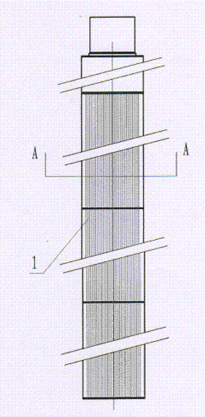
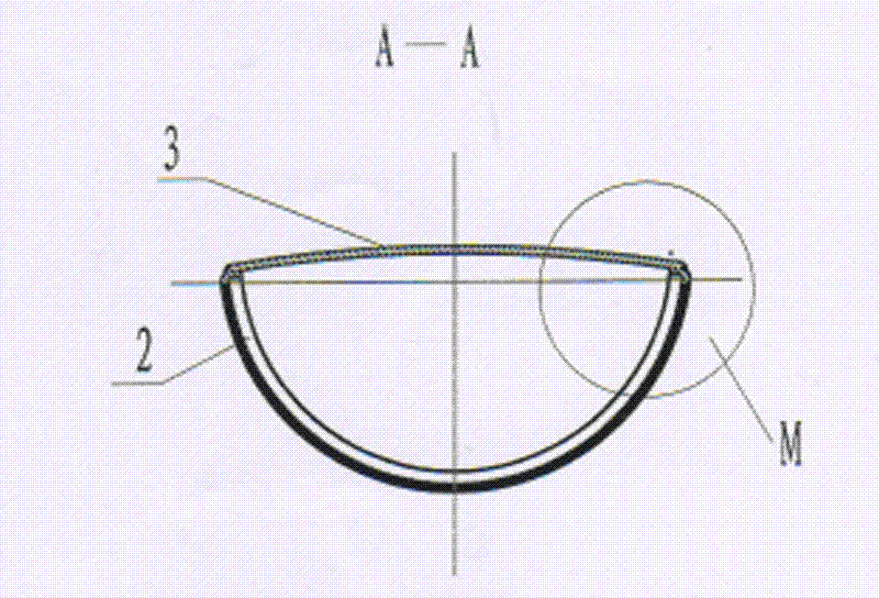
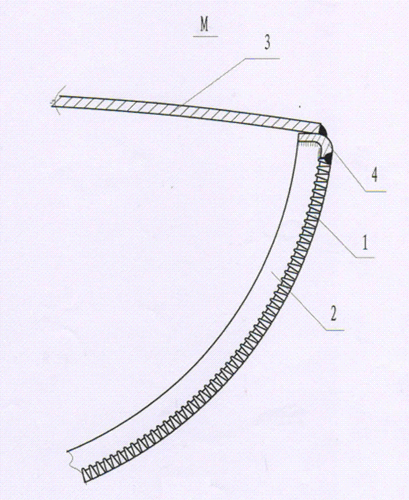
[0013] The arc-shaped fan-shaped distribution tube of strip mesh includes fan-shaped support ring 2, support ring connection frame 4, arc-shaped back shell plate 3, and mesh strip 1. There are multiple fan-shaped support rings 2, which are evenly arranged in the support ring connection frame 4 at equal distances, and welded on the support ring connection frame 4, and a plurality of mesh bars 1 are axially arranged at a set distance. On a fan-shaped support ring 2 arranged equidistantly, its cross-section of the mesh bar 1 is an isosceles triangle, and the inverted triangle and the trapezoidal support ring 2 are welded vertically at 90° to form an arc fan-shaped strip net. The arc-shaped rear shell plate 3 of the overall structure is fixedly connected to the support ring connection frame 4, forming a strip-shaped arc-shaped fan-shaped distribution tube.


PUM


Abstract

Disclosed is a cambered-surface sector-shaped cylinder with a strip-shaped net, comprising a plurality of sector-shaped supporting rings, a supporting ring connecting frame, an arc-shaped back housing plate, and net strips, wherein the plurality of sector-shaped supporting rings are equidistantly arranged inside the supporting ring connecting frame uniformly and welded on the supporting ring connecting frame, the plurality of net strips are arranged at set intervals and welded on the equidistantly arranged sector-shaped supporting rings to form a cambered-surface sector-shaped strip-shaped net, and the arc-shaped back housing plate is fixedly connected with the supporting ring connecting frame. According to the invention, as the arc-shaped back housing plate is adopted and thickened, the wear resistance and the high temperature resistance of a back plate is improved. The formed cambered-surface sector-shaped strip-shaped net has a good impact resistance, a good distortion resistance, a good bending resistance and a good tensile resistance and has no deformation, cracking or the like when the temperature is changed. In addition, the strip-shaped net is axially arranged and gaps are uniform and vertical, so the pressure drop is avoided, the flow resistance of a catalyst is reduced and the friction and the collision to the catalyst are reduced. The service life of the cambered-surface sector-shaped cylinder with a strip-shaped net of the invention is more than 20 years.

Description

technical field [0001] The invention relates to a material distribution cylinder in a reforming reactor, in particular to a fan-shaped distribution cylinder with a strip-shaped mesh arc surface. Background technique [0002] In the past, the fan-shaped distribution cylinder of the domestic reforming reactor was completely formed by cold-punching a number of long through-holes on a stainless steel plate with a thickness of 1.2-1.5 mm and then stamping it. The thin plate has poor impact resistance and pressure resistance, and is prone to deformation and bending defects. There are burrs on the edge of the punched through hole, and its stretching makes the surface uneven and deformed. The through hole is a long hole arranged horizontally, which has friction and collision with the fluidized bed catalyst, resulting in an increase in the breakage rate of the catalyst and increasing the replenishment of the catalyst. . The fan-shaped cylinder is subjected to high temperature, corro...

Claims


Application Information

Patent Timeline
Patent Type & Authority Applications(China)
IPC IPC(8): B01J8/12
Inventor 张富成
Owner LIAONING QIANGSEN SIFTER MFG
Learn More