Waterborne flying ship
A technology for watercraft and ships, which is applied in the direction of hull, ship propulsion, and ship parts, etc., can solve the problems of low water-repellent driving efficiency, reducing the water-repelling efficiency of driving wheels, and weakening a small number of benefits.
- Summary
- Abstract
- Description
- Claims
- Application Information
AI Technical Summary
Problems solved by technology
Method used
Image
Examples
Embodiment 1
[0165] Such as Figure 4 As shown, the airship of the present embodiment includes parts such as a streamlined hull 6, a power system containing a centrifugal turbine, a high-speed driving balance system, and a rudder. The centrifugal turbine is installed at the bottom of the hull, and part of the turbine blades 2 extend downward. The exposed part is exposed below the bottom of the ship, and the height of the exposed part is preferably greater than a quarter of the diameter of the turbine and less than the radius of the turbine; the rudder is installed at the stern of the hull and is centered.
[0166] The high-speed driving balancing system of the present embodiment includes horizontal balancing composed of synchronously rotating centrifugal turbines symmetrically arranged on both sides of the hull, and longitudinal balancing composed of two rows of centrifugal turbines respectively arranged at the front and rear of the hull.
[0167] The rudder of the present embodiment is ma...
Embodiment 2
[0174] Figure 40 and Figure 41 As shown, the difference between the present embodiment and the above-mentioned first embodiment is that the water flying ship of the present embodiment is respectively provided with three or more rows of centrifugally driven turbines at the front and back of the hull.
Embodiment 3
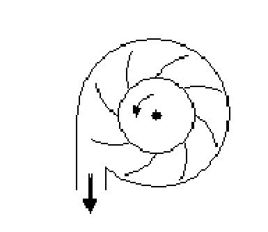
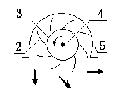
[0176] Such as image 3 and Figure 6 , Figure 8 As shown, the difference between this embodiment and the above two embodiments is that there is a fairing 5 above the centrifugal turbine in this embodiment, and the turbine part that is larger than the radius of the centrifugal turbine is sealed in the upper fairing 5, accounting for less than the centrifugal turbine. The turbine blade 2 of the part below the turbine radius protrudes downwards from the fairing 5 and is exposed below the bottom of the ship, and the exposed turbine blade 2 height is greater than 1 / 4 of the turbine diameter; the centrifugal turbine used in the present invention corresponds to the conventional centrifugal turbine. The location of the water pump outlet (or the exhaust outlet of a conventional centrifugal air pump) (see Figure 1-2 ), opening a larger opening (see figure 2 and image 3 ), the opening is located at the bottom of the ship (see Figure 6 , Figure 7 ), the turbine blade 2 is exp...
PUM
 Abstract
Description
Claims
Application Information
 - R&D
- Intellectual Property
- Life Sciences
- Materials
- Tech Scout
- Unparalleled Data Quality
- Higher Quality Content
- 60% Fewer Hallucinations
Browse by: Latest US Patents, China's latest patents, Technical Efficacy Thesaurus, Application Domain, Technology Topic, Popular Technical Reports.
© 2025 PatSnap. All rights reserved.Legal|Privacy policy|Modern Slavery Act Transparency Statement|Sitemap|About US| Contact US: help@patsnap.com


