Supporting device for arched steel among beam columns

A support device and arch steel technology, which is applied to arch structures, building components, dome structures, etc., can solve the problem of reducing beam section size and reinforcement amount, large main beam section size and reinforcement amount, and reducing Problems such as the internal force of the main beam, to achieve the effect of reducing the cost of the project, reducing the internal force, reducing the size of the beam section and the amount of reinforcement

Inactive Publication Date: 2012-09-26
SHANGHAI UNIV
View PDF5 Cites 3 Cited by
  • Summary
  • Abstract
  • Description
  • Claims
  • Application Information

AI Technical Summary

Problems solved by technology

[0003] The purpose of the present invention is to overcome the problems of the large cross-sectional size of the main beam and the large amount of reinforcement in the current design of large underground garages, and provide an arched steel support device between beams and columns, which can effectively adjust and reduce the internal force of the main beam, and greatly reduce the cross-section of the beam Dimensions and amount of reinforcement, resulting in cost savings

Method used


Image

  • Supporting device for arched steel among beam columns
  • Supporting device for arched steel among beam columns
  • Supporting device for arched steel among beam columns

Examples


Embodiment 1

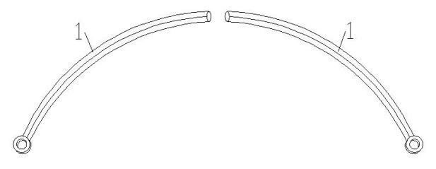
[0030] see Figure 1-Figure 5 , the arched steel support device between beams and columns is composed of two arc-shaped steel pipes (1), frame columns (2) and main beams (5), characterized in that one end of the two arc-shaped steel pipes (1) is respectively It is hinged with the frame columns (2) on both sides, and the other end is hinged with the lower part of the midpoint of the main beam (5) to form a two-hinge arc arch.

Embodiment 2

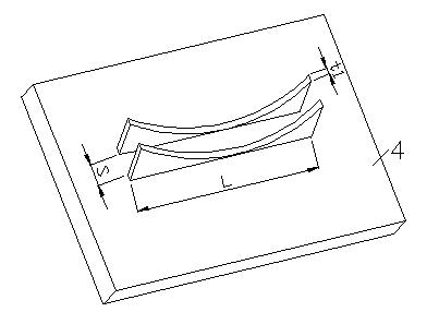
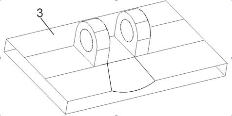
[0032] see Figure 1-Figure 5 , this embodiment is basically the same as the first embodiment, the special feature is: the structure of connecting the two arc-shaped steel pipes (1) with the frame column (2) and the main beam (5) is: the two arc-shaped steel pipes (1) are connected A small steel ring is welded to one end of the steel pipe (1), a hinge seat (3) is embedded in the frame column (2), and a shaft pin is inserted into the inner hole of the small steel ring at the end of the steel pipe (1). and the pin hole on the hinge seat (3) to realize the hinge connection between the steel pipe (1) and the frame column (2), and the other end of the steel pipe (1) is embedded with one of the midpoints of the main beam (5). The parts (4) are connected by welding to realize the hinge connection between the steel pipe (1) and the main beam (5).

Embodiment 3

[0034] see Figure 1-Figure 6 , the arched steel support device between beams and columns, including figure 1 Two rounded steel tubes shown. Pre-embedded below the midpoint of the main beam figure 2 Embedded parts shown, embedded on the side of the frame column image 3 The hinge seat shown, on the premise of meeting the clearance requirements of the underground garage, is set between the frame column and the main beam through the embedded parts as shown in the figure below. Figure 4 The arched steel support is shown, one end of the arched steel tube is hinged with the frame column, and the other end is hinged with the lower part of the midpoint of the main beam. A shaft pin is inserted into the inner hole of the small steel ring at the end of the arched steel pipe and image 3 The pin hole on the embedded part as shown, realizes the hinge connection between one end of the arched steel pipe and the frame column. The other end of the arched steel pipe is connected with t...


PUM


Abstract

The invention discloses a supporting device for arched steel among beam columns. The supporting device can effectively control the internal force of a girder of an underground garage and comprises two circular arc steel tubes, framework columns and a girder, wherein one ends of the two circular arc steel tubes are respectively hinged with the framework columns on two sides; and the other ends of the two circular arc steel tubes are hinged with the lower part of a middle point of the girder to form two hinged circular arches. According to the supporting device disclosed by the invention, the internal force of the girder can be effectively adjusted and reduced, and the section size and the reinforcement quantity of the beams are greatly reduced, so as to achieve the aim of reducing the structure cost.

Description

technical field [0001] The invention is mainly used in the field of civil engineering, especially in the construction of large underground garages, for reducing the cross-sectional size of the main beam, thereby reducing the floor height and saving the cost. The invention can be used for new construction and reinforcement of existing buildings. Background technique [0002] At present, large underground garages mostly use primary and secondary beam structures. Due to the large space requirements of the underground garage and the large overlying soil load, the main beam span is large and the internal force in the beam is very large, so the bearing capacity of the main beam and the deformation and crack development are proposed. In order to meet the requirements of the specification, the conventional practice is to increase the cross-sectional size of the main beam, which will increase the amount of reinforcement in the main beam, which will lead to increased basement floor he...

Claims


Application Information

Patent Timeline
Patent Type & Authority Applications(China)
IPC IPC(8): E04B1/32E04B1/58
Inventor 朱杰江王彩霞戴李鹃洪锡烽张磊
Owner SHANGHAI UNIV
Why Eureka
Try Eureka