Pipe joint

A technology for pipe joints and connecting pipes, applied in the field of pipe joints, can solve the problems of many constraints, unable to obtain the sealing effect of sealing rings, etc., and achieve the effect of easy elastic deformation

Inactive Publication Date: 2012-09-26
ARONKASEI
View PDF17 Cites 12 Cited by
  • Summary
  • Abstract
  • Description
  • Claims
  • Application Information

AI Technical Summary

Problems solved by technology

As a result, in a pipe joint of the type having a fixed locking ring, a sufficient sealing effect due to the sealing ring cannot be obtained. In a

Method used


Image

  • Pipe joint
  • Pipe joint
  • Pipe joint

Examples


Example Embodiment

[0140] Hereinafter, an in-line pipe joint according to an embodiment of the present invention will be described in detail with reference to the drawings. In addition, the present invention is not limited to the embodiments shown below, and various modifications can be made without departing from the technical idea of ​​the present invention.

[0141] [Example]

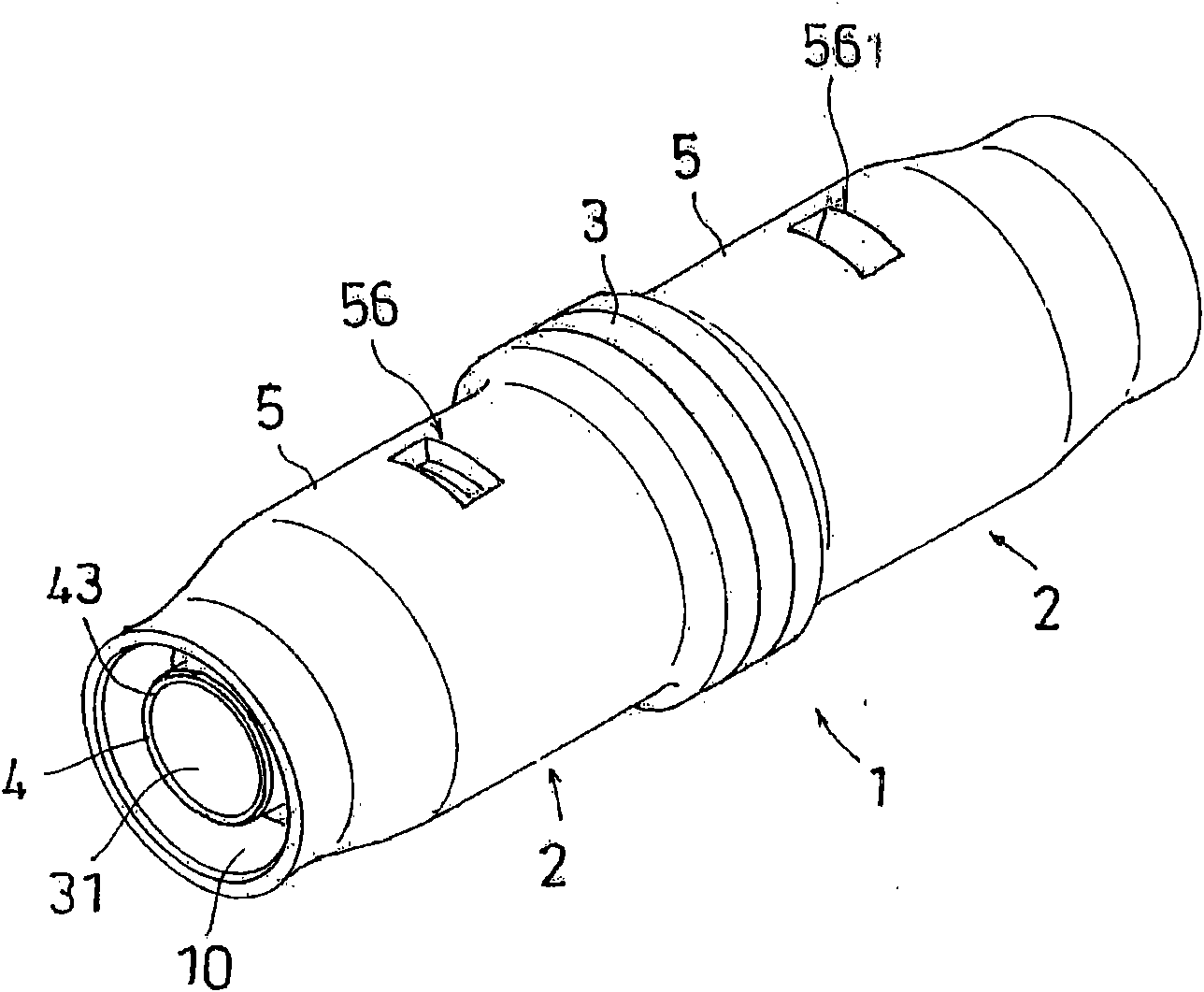
[0142] figure 1 It is a perspective view showing the whole of the in-line pipe joint 1 according to a preferred embodiment of the present invention. reference figure 1 It can be seen that the pipe joint 1 of the present invention has two connecting pipe insertion sockets 2 in the I-shape. However, the pipe joint of the present invention is not limited to the type having two connecting pipe insertion sockets 2. The pipe joint of the present invention also includes, for example, the connecting pipe insertion socket 2 of the present invention is arranged on only one side and the other side is arranged. Generally, the receivi...


PUM


Abstract

The invention provides a bulk type pipe joint. After being connected with a connecting pipe and acted by a force in a drawing directional, the pipe joint can reliably and fixedly clamp and block the connecting pipe, and the inserting resistance caused by teeth or claws of a locking ring when the connecting pipe is inserted is small. The bulk type pipe joint provided by the invention is characterized in that the connecting pipe accommodating part of the pipe joint is provided with the locking ring, and the locking ring is provided with a first claw part used for pressing the circumference surface of the connecting pipe when the connecting pipe is inserted and a second claw part used for clamping and blocking the connecting pipe when the connecting pipe is drawn, so that the connecting pipe is inserted so as to shift toward the drawn direction, the first claw part clamps and blocks the connecting pipe, and the interaction of the second claw part and a surrounding cone wall is deflected in a manner of pressing the circumferential surface of the connecting pipe.

Description

technical field [0001] The present invention relates to a pipe joint for connecting a connecting pipe in a one-touch type. In particular, a connecting pipe receiving portion of the pipe joint is provided with a first claw for pressing the peripheral surface when the connecting pipe is inserted and a connecting pipe. The locking ring used to lock the second claw of the connecting pipe when the pipe is pulled out. It also relates to a pipe joint, which is characterized in that, when the connecting pipe is inserted and moved in the pulling direction, the first claw is locked on the connecting pipe, and the second claw interacts with the surrounding cone wall to crimp the connecting pipe. The way of the circumference of the displacement. Background technique [0002] A pipe connector for connecting pipes in a push-in connection is known at present. For example, JP Unexamined Publication No. 4-18793 (Patent Document 1), JP Unexamined Publication No. 2001-193883 (Patent Document...

Claims


Application Information

Patent Timeline
IPC IPC(8): F16L21/08F16L37/12F16L37/091
Inventor 太田浩司水野宏俊北岛典和中居义贵长谷川博一
Owner ARONKASEI
Why Eureka
Try Eureka