Backlight module

A backlight module and backplane technology, applied in the field of backlight modules, can solve problems such as high cost, difficult operation, and affecting backlight effects, and achieve the effects of low cost, convenient operation, and simplified manufacturing process

Active Publication Date: 2012-09-26
TCL CHINA STAR OPTOELECTRONICS TECH CO LTD
View PDF4 Cites 19 Cited by
  • Summary
  • Abstract
  • Description
  • Claims
  • Application Information

AI Technical Summary

Problems solved by technology

This riveting positioning method is difficult to operate, the cos

Method used


Image

  • Backlight module
  • Backlight module
  • Backlight module

Examples


Embodiment Construction

[0023] In order to further illustrate the technical means adopted by the present invention and its effects, the following describes in detail in conjunction with preferred embodiments of the present invention and accompanying drawings.

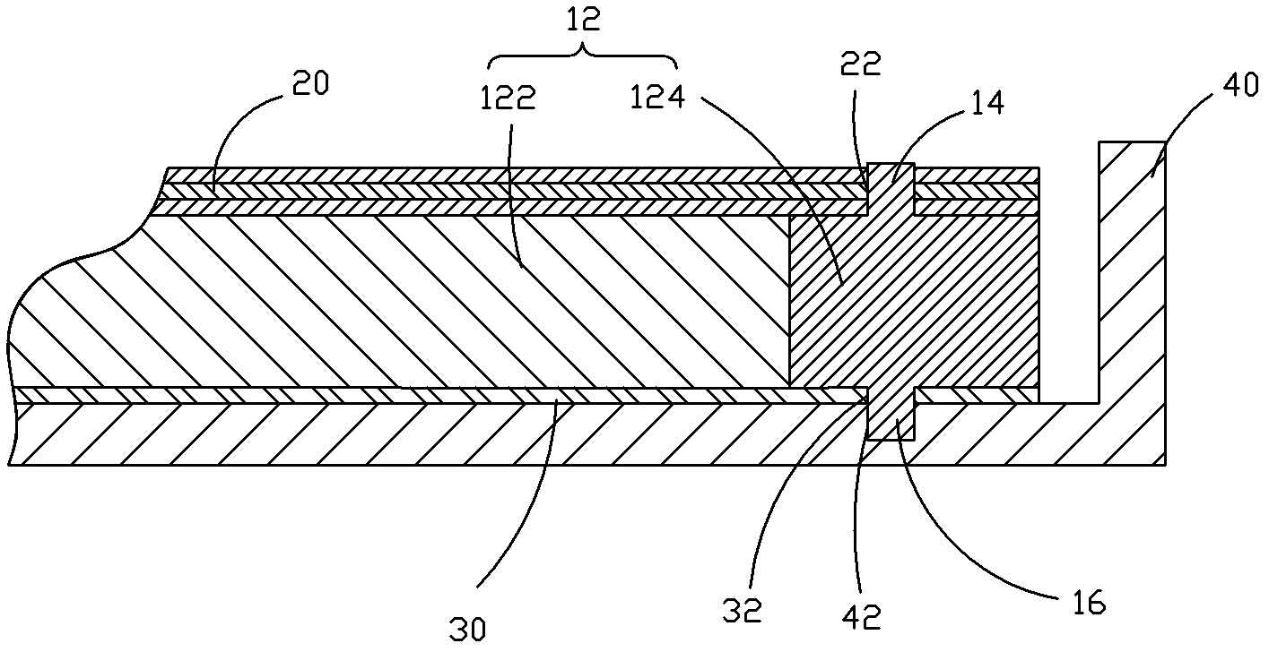
[0024] see Figures 1 to 2 , the backlight module provided by the present invention, which includes: a backplane 40, a reflective sheet 30 disposed in the backplane 40, a light guide plate 10 disposed on the reflective sheet 30, and an optical film 20 disposed on the light guide plate 10, The light guide plate 10 , the optical film 20 and the reflection sheet 30 are all disposed in the back plate 40 .

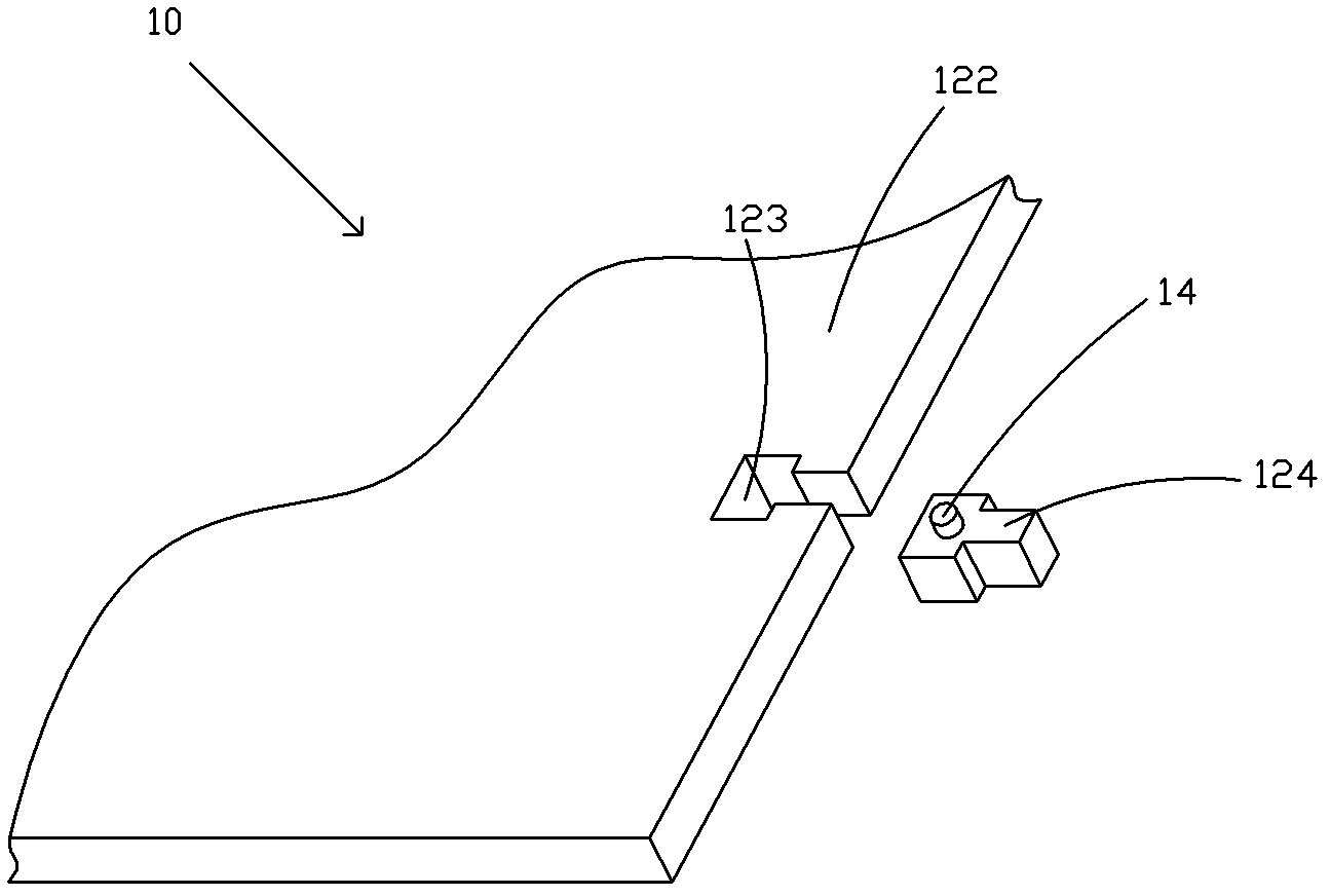
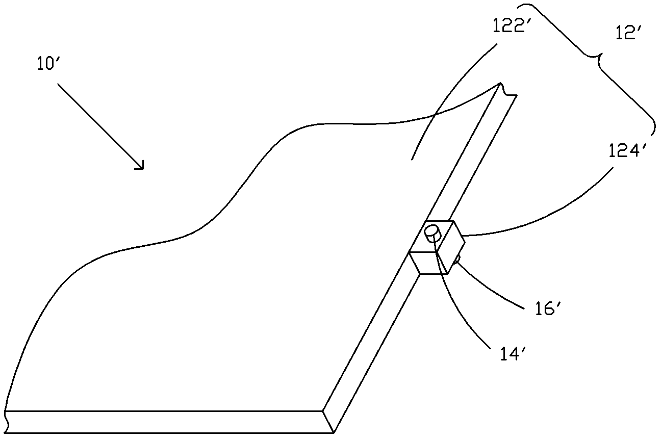
[0025] The light guide plate 10 includes a main body 12, and several upper positioning posts 14 and lower positioning posts 16 protruding from the upper and lower surfaces of the main body 12. The main body 12 includes a base 122 and several positioning posts mounted on the base 122. The positioning part 124, the upper and lower positioning co...


PUM


Abstract

The invention provides a backlight module, which comprises a backboard, a reflection sheet arranged in the backboard, a light guide board arranged on the reflection sheet and an optical membrane arranged on the light guide board, wherein the light guide board comprises a body, a plurality of upper positioning columns and a plurality of lower positioning columns; the plurality of upper positioning columns and the plurality of lower positioning columns are protruded on the upper surface and the lower surface of the body; first positioning holes are formed on the optical membrane corresponding to the upper positioning columns; second positioning holes are formed on the reflection sheet corresponding to the reflection sheet; positioning slots are formed on the backboard corresponding to the lower positioning columns; the first positioning holes in the optical membrane are correspondingly sleeved on the upper positioning columns of the light guide board; and the lower positioning columns of the light guide board pass through the second positioning holes of the corresponding reflection sheet and are arranged in the positioning slots on the backboard. According to the invention, rivet columns in the prior art are not used; the manufacturing process of the backlight module is simplified; the backlight module is simple in structure and is low in cost; and furthermore, the positioning columns are made of materials which are the same as that of the light guide board so that the backlight effect cannot be influenced.

Description

technical field [0001] The invention relates to the field of liquid crystal display, in particular to a backlight module. Background technique [0002] A liquid crystal display (LCD, Liquid Crystal Display) has many advantages such as a thin body, power saving, and no radiation, and has been widely used. Most of the liquid crystal display devices currently on the market are backlight liquid crystal displays, which include a liquid crystal panel and a backlight module. The working principle of the LCD panel is to place liquid crystal molecules between two parallel glasses. There are many small vertical and horizontal wires between the two glasses. The direction of the liquid crystal molecules is controlled by electrifying or not, and the light from the backlight module is refracted out to produce picture. Since the liquid crystal panel itself does not emit light, the light source provided by the backlight module is needed to display images normally. Therefore, the backlight...

Claims


Application Information

Patent Timeline
IPC IPC(8): F21S8/00F21V13/00F21V17/10G02F1/13357
CPCG02B6/0088G02F2001/133322G02F1/1335G02F1/133308G02F2001/133317G02B6/00G02F1/133317G02F1/133322
Inventor 黄冲
Owner TCL CHINA STAR OPTOELECTRONICS TECH CO LTD
Why Eureka
Try Eureka